Experiment #5: Photorefractive effect and its applications.
advertisement

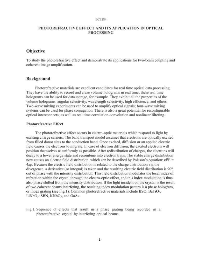
ECE184 PHOTOREFRACTIVE EFFECT AND ITS APPLICATION IN OPTICAL PROCESSING Objective To study the photorefractive effect and demonstrate its applications for two-beam coupling and coherent image amplification. Background Photorefractive materials are excellent candidates for real time optical data processing. They have the ability to record and erase volume holograms in real time; these real time holograms can be used for data storage, for example. They exhibit all the properties of the volume holograms: angular selectivity, wavelength selectivity, high efficiency, and others. Two-wave mixing experiments can be used to amplify optical signals; four-wave mixing systems can be used for phase conjugation. There is also a great potential for reconfigurable optical interconnects, as well as real time correlation-convolution and nonlinear filtering. Photorefractive Effect The photorefractive effect occurs in electro-optic materials which respond to light by exciting charge carriers. The band transport model assumes that electrons are optically excited from filled donor sites to the conduction band. Once excited, diffusion or an applied electric field causes the electrons to migrate. In case of electron diffusion, the excited electrons will position themselves as uniformly as possible. After redistribution of charges, the electrons will decay to a lower energy state and recombine into electron traps. The stable charge distribution now causes an electric field distribution, which can be described by Poisson’s equation: ε∇E = 4πρ. Because the electric field distribution is related to the charge distribution via the divergence, a derivative (or integral) is taken and the resulting electric field distribution is 90º out of phase with the intensity distribution. This field distribution modulates the local index of refraction within the crystal through the electro-optic effect, and this index modulation is thus also phase shifted from the intensity distribution. If the light incident on the crystal is the result of two coherent beams interfering, the resulting index modulation pattern is a phase hologram, or index grating (see Fig.1). Common photorefractive materials include BSO, BaTiO3, LiNbO3, SBN, KNbO3, and GaAs. Fig.1. Sequence of effects that result in a phase grating being recorded in a photorefractive crystal by interfering optical beams. 1 I(x) Excitation of charges by optical field optical field I(x) Diffusion or drift of excited charges ρ(x) \ E(x) Resulting charge distribution after electrons recombine Electric field produced by the space charge distribution: ε ∇E= 4πρ Δn(x) Modulation of refraction index 2 Two-Beam Coupling The hologram recorded in the photorefractive medium can be used to couple the energy from a pump beam into a signal beam. The behavior of the crystal can be described by solving the wave equation (1) with index variation given by (2) assuming an optical field composed of two plane waves that have slowly varying amplitudes compared to the wavelength (i.e. ) (3) where the subscripts g, p, and s refer to grating, pump, and signal respectively. It is possible to evaluate the wave equation with the total optical field and collect terms with exponents that are alike (same frequency). By assuming that Ψ p » Ψ s , proper crystal orientation, and neglecting terms in the equation that are second derivatives of Ep or Es , the end result predicts that energy from one plane wave will be transferred to the other, described by (4) This coupling of energy from one beam to another is highly dependent on the interaction distance L and the angles α p , α s , θ at which the pump and signal beams interact. The orientation of the crystal indicates the direction of power transfer. These parameters are conventionally measured inside the crystal, and because the index of refraction is so high (2.0 < n < 3.5) inside most of the photorefractive materials, the parameters differ greatly from those measured externally (see Fig. 2). The relationship between the external and internal vectors must obey Snell's law, (5) and the grating vector must obey the Bragg condition (see Fig. 3) (6) 3 A Fig.2. Two-beam coupling geometry in a photorefractive crystal. Note the direction for positive measurement of angles α p and α s . kgrating Fig.3. Bragg condition for the grating, pump, and signal vectors. It should be noted that the phase shift of the index grating has an important effect on the coupling of two beams: as the pump beam propagates through the index modulated medium, it will be partially deflected into the signal beam direction in such way that its superposition onto the propagating signal beam leads to constructive interference, and hence the signal beam will experience gain. By defining Is(0) as the signal beam intensity at the input before the crystal, Is(L) as the signal beam intensity at the output after the crystal, and likewise for the pump beam, the gain coefficient Г and gain G can be defined as (7) 4 where the beam ratio r is defined as (8) The gain characteristics are plotted as function of beam ratios in Fig. 4. Fig.4. Plot of signal beam gain G as a function of input beam ratio r. As with all amplifying media, there is a saturation point beyond which no significant gain will occur, and this is achieved when reГL « 1, and (9) As can be deduced from Fig. 4, the saturation occurs when r « 1. The interaction distance L is defined to be the distance over which the beams interfere with each other, measured along the bisector between the signal and pump beam directions. With a rectangular or cubic shaped crystal, this distance will vary greatly depending on the incident angles and amount of refraction the beams encounter (see Fig.5). As can be seen from this figure, L cosβ =a L sinβ= b (β < β') (β > β') (10) where β' =tan-1(b/a). In addition to the effect of L due to the angle β between the grating and the crystal axis c, the gain coefficient also depends on the angle 2θ between the interacting beams (as θ is related to the grating frequency). A plot of this dependence for a typical BaTi03 crystal is shown in Fig.6. 5 Fig.5. Different interaction distances for different interaction geometries: (a) (β<β'), (b) (β>/β'). Fig.6. Plot of gain coefficient dependence on β and θ for photorefractive BaTiO3 with λ = 514nm, no = 2.488, ne = 2.424, N = 2x1016 cm-3, r13 = 8, r33 = 28, r42 = 820pm/V, εo = 4300 ε, and εe = 106ε . 6 Experimental procedure. A. Determine the optical axis c of the crystal and the direction of energy transfer. 1. Place BaTiO3 crystal between two crossed polarizers (see Fig.8). Fig.8. Optical setup to find the optical axis of the crystal. 2. Send laser beam through a system and place a diffuser close to the crystal (but do not touch the crystal). 3. Rotate the crystal until the isogyre pattern (see Fig.9) is observed, this indicates that the optical axis c is along the laser beam. Fig.9. Isogyre pattern. 4. Remove the diffuser and polarizers. Rotate the crystal such that the optical axis is making about 30º angle with the direction of the laser beam. Observe the beam dissipation (so called beam “fanning”) by the crystal. Notice the “fanning” direction regarding to the incident beam. B. Two-Beam Coupling The optical system for performing two-beam coupling is shown in Fig. 10. The angle θ can be varied by changing the distance between the beamsplitter BS and the Mirror. The variable attenuator VA controls the beam ratio r. 7 Fig.10. Optical setup for two-beam coupling. 1. Understand the optical setup and its essentials, such as: - crystal orientation and energy transfer from pump to signal, - angle between signal and pump beam (external angle 2θext is angle in the air; and internal angle 2θ - in the crystal), - angle between optical axis c and grating vector kg (in air it is βext, in the crystal it is βint). 2. - Check that optical path difference between signal and pump beams is close to zero; - check that the angle between signal and pump is 2θext = 20º; - check that 0º mark on the crystal rotation stage corresponds to βext = 0º. 3. Measure the pump and the signal power before the crystal by using the photodetector with attached iris (keep the same iris opening during the experiment, about 3mm in diameter). Set pump at 5mW and signal corresponding to r = 5x10⁻³. 4. Measure the signal beam after the crystal while the pump is blocked. Open pump beam and observe gain in the signal. The signal will fluctuate, take maximum reading. Calculate gain G. 5. By rotating the crystal change βext from 0º to 90º and determine the signal gain G as function of βext. Find angle βext giving the maximum gain. 6. Calculate corresponding βint and interaction distances L inside the crystal (crystal size is 4mm ×5.5mm and refractive index ne = 2.42). Calculate gain coefficient Γ and plot Γ as function of βint. 7. For optimal βext, vary the beam ratio r from 10-2 to 10-6 and measure the signal gain G. 8. Plot G (in dB) as function of log(r). Can you see the gain saturation? If not, explain why. 8 C. Coherent Image Amplification 1. Set up 4F imaging system. 2. Set pump power to 5mW and signal power to 5μW before the crystal. (Because the signal beam is focused into the crystal, the actual beam ratio is unknown inside the crystal.) 4. Place resolution target into the object plane. Observe image amplification and find resolution limit of the photorefractive amplifier. 5. Observe the hologram recording and erasing in the crystal by blocking the signal beam. Fig.11. Coherent optical amplification system. 9


