Pipelined Parallel FFT Architectures Using Folding Transformation
advertisement
Pipelined Parallel FFT Architectures Using Folding
Transformation
Mr.R.V.TALATHI
Department of E&TC Engineering
VLSI & EMBEDDED SYSTEM
PVPIT, PUNE
rohitvtalathi@gmail.com
Abstract - In this paper, the approach is to develop
parallel pipelined architectures for the Fast Fourier
transform (FFT) is presented. The folding transformation
and register minimization techniques are proposed for
designing FFT architectures. Novel parallel-pipelined
architectures for the computation of fast Fourier
transform are derived The proposed architectures exploit
redundancy in the computation of FFT samples to reduce
the hardware complexity. A comparison is drawn between
the proposed designs and the previous architectures. The
power consumption can be reduced up to 37% and 50% in
2-parallel CFFT and RFFT architectures, respectively.
Keywords– Fast Fourier Transform (FFT), folding, register
minimization, low power.
1. INTRODUCTION
DFT is one of the most important tools in the field of digital
signal processing. Several Fast Fourier Transform (FFT)
algorithms have been developed over the years due to its
computational complexity. FFT plays a critical role in
modern digital communications such as Digital Video
Broadcasting (DVB) and Orthogonal Frequency Division
Multiplexing (OFDM) systems. Algorithms such as radix-4
,[1] split-radix [2] and radix-2^2 [3] have been developed
based on the basic radix-2 FFT approach. The one of the
most classical approaches for pipelined implementation of
radix-2 FFT is Radix-2 multi-path delay commutator
(R2MDC) [4]. A standard usage of the storage buffer in
R2MDC leads to the Radix-2 Single-path delay feedback
(R2SDF) [5 ]architecture with reduced memory.
In additional, most of these hardware architectures are not
fully utilized and require high hardware complexity. In the
period of high speed digital communications, the high
throughput and low power designs are essential to meet the
speed and power requirements while keeping the hardware
overhead to a minimum. In this paper, a new approach to
design the architecture from the FFT flow graphs is
presented. Folding transformation [6] and register
minimization technique [7][8] are used to derive several
known FFT architectures.
Prof..S.M.Kulkarni
Department of E&TC Engineering
PVPIT Bavdhan
Pune India.
smk_1@rediffmail.com
2. FOLDING TRANSFORMATION
In the folding transformation, many butterflies in
the same column can be mapped to one butterfly unit. If the
FFT size is N, a folding factor of N/2 leads to 2-parallel
architecture and in another design, a folding factor of N/4
leads to design 4-parallel architectures in which four
samples are processed in the same clock cycle. Various
folding sets lead to a family of FFT architectures [9].
2.1 FFT Architectures Design Techniques
In this section, the folding transformation method and
register minimization to derive several known FFT
architectures is illustrated in general.[9] The process is
described using an 8-point radix-2 DIF FFT as an example.
It can be extended to other radices in a similar fashion.
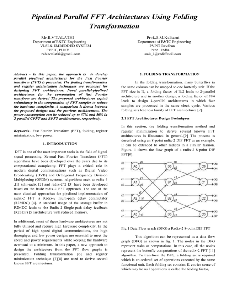
Figure. 1 shows the flow graph of a radix-2 8-point DIF
FFT[9].
Fig.1 Data Flow graph (DFG) a Radix-2 8-point DIF FFT
This algorithm can be represented as a data flow
graph (DFG) as shown in fig. 1. The nodes in the DFG
represent tasks or computations. In this case, all the nodes
represent the butterfly computations of the radix-2 FFT [11]
algorithm. To transform the DFG, a folding set is required
which is an ordered set of operations executed by the same
functional unit. Each folding set contains K entries some of
which may be null operations is called the folding factor,
number of delays. The folded delays for the
pipelined DFG are
DF (A0 - B0) = 2
DF (A0 - B2) = 4
DF (A1 - B1) = 2
DF (A1 - B1) = 4
DF (A2 - B0) = 0
DF (A2 - B2) = 2
DF (A3 - B1) = 0
DF (A3 - B3) = 2
DF (B0 - C0) = 1
DF (B0 - C1) = 2
DF (B1 - C0) = 0
DF (B1 - C1) = 1
DF (B2 - C2) = 1
DF (B2 - C3) = 2
DF (B3 - C2) = 0
DF (B3 - C3) = 1…(3)
3. FFT DESIGN TECHNIQUES
Fig.2 pipelined DFG of a 8-point DIF-FFT as a
preprocessing step for folding
The Fig 3. Shows block diagram of folding
architectures of FFT techniques.
For example, consider the folding set A = {ϕ, ϕ, ϕ,
ϕ, A0, A1, A2, A3} for K=8. The operation A0 belongs to
the folding set A with the folding order 4. The functional
unit executes the operations A0, A1, A2, and A3 at the
respective time instances and will be idle during the null
operations. The systematic folding techniques are used to
derive the 8-point FFT architecture. Consider an edge e
connecting the nodes U and V with w (e) delays.
The folding equation (1) for the edge e is
DF (U - V) = K w(e)-PU + v - u (1)
Where PU is the number of pipeline stages in the hardware
unit which executes the node U. By using folding sets,
folding equations are derived with negative delays (w/o
pipeline) and non-negative delays (with pipeline or
retiming). Consider folding of the DFG in fig.2 with the
folding sets
A = {ϕ, ϕ, ϕ, ϕ, A0, A1, A2, A3}
B = {B2, B3, ϕ, ϕ, ϕ, ϕ, B0, B1}
C = {C1, C2, C3, ϕ, ϕ, ϕ, ϕ, C0}.
Assume that the butterfly operations do not have any
pipeline stages, i.e., PA=0, PB=0, PC=0.Retiming and/or
pipelining [10] can be used to either satisfy DFU-V) ≥0 or
determine that the folding sets are not feasible .The negative
delays on some edges can be observed. The equations are
DF (A0 - B0) = 2
DF (A0 - B2) = - 4
DF (A1 - B1) = 2
DF (A1 - B1) = - 4
DF (A2 - B0) = 0
DF (A2 - B2) = - 6
DF (A3 - B1) = 0
DF (A3 - B3) = - 6
DF (B0 - C0) = 1
DF (B0 - C1) = - 6
DF (B1 - C0) = 0
DF (B1 - C1) = - 7
DF (B2 - C2) = 1
DF (B2 - C3) = 2
DF (B3 - C2) = 0
DF (B3 - C3) =1…. (2)
The DFG can be pipelined is shown to
ensure that folded hardware has non-negative
Fig. 3 Block diagram of FFT design techniques
The technique for minimizing register is lifetime
analysis which analyzes the time for when a data is
produced (Tinput) and when a data finally is consumed
(Toutput).
T input = u + PU
(4)
T output = u + PU + maxv {DF (U→V)}
(5)
where u is the folding order of U and PU is the number of
pipelining stages in the functional unit that executes u. From
(3) the 24 registers are required to implement the folded
architecture.
4. REGISTER MINIMIZATION TECHNIQUES
In Lifetime Analysis the no. of live variables at
each time unit is computed and the maximum no. of live
variables at any time unit is determined. this is the minimum
no. of registers required to implement the DSP program .
Lifetime analysis technique is used to design the
folded architecture with minimum possible registers. For
example, in the current 8-point FFT design, consider the
variables y0, y1,. . . y7, i.e., the outputs at the nodes
A0,A1,A2,A3 respectively. It takes 16 registers to
synthesize these edges in the folded architecture. The
minimum number of registers required to implement this
DSP program is the maximum no. of live variables at any
time unit.
NODE
y0
y1
y2
y3
y4
y5
y6
y7
Tinput Toutput
4
6
5
7
4
8
5
9
6
8
7
9
F
i
g. 6 Register allocation table
Fig.4 Linear lifetime table.
The linear lifetime table and lifetime chart for these
variables is shown in figure. 4 and figure. 5. From the
lifetime chart,[4] it can be seen that the folded architecture
requires 4 registers as opposed to 16 registers in a
straightforward implementation. The next step is to perform
forward-backward register allocation.
From the allocation table in Fig.6 and the folding equations,
the final architecture in Fig. 7 can be synthesized and can be
derived by minimizing the registers on all variables at once.
The hardware utilization is only 50% in the derived
architecture the pipelined parallel FFT architectures are
presented by using this methodology.
Fig.5 Linear lifetime chart
Register allocation can be performed using an allocation
table .the allocation scheme dictates how the variables are
assigned to registers in the allocation table. The allocation
table that uses the forward-backward scheme to allocate the
data for the 3 x 3 matrix transposer is shown in fig. 6.[6][8].
1) Determine the minimum number of registers using
lifetime analysis.
2) Input each variable at the time step corresponding
to the beginning of its lifetime.
3) Each variable is allocated in a forward manner until
it is dead or it reaches the last register.
4) Since the allocation is periodic the allocation of the
current iteration also repeats itself in subsequent
iterations.
5) For variables that reach the last register and are not
yet dead the remaining life period is calculated and
these variables are allocated to a register in a
backward manner on a first come first served basis.
6) Repeat steps 4 & 5 as required until the allocation
is complete.
Fig.7 Folded Architecture
5. COMPARISON AND ANALYSIS
The hardware complexity of the architectures
depends on the required no. of multipliers, adders, and delay
elements. The performance is presented by throughput. The
no. of multiplier required in the radix 2^4 architecture is less
than previous designs. The proposed FFT architecture leads
to low hardware complexity.
Architectures
Multipliers
Adders
Delays
R2MDC
2(log4N-1)
2(log4N-1)
(log4N-1)
(log8N-1)
2(log8N-1)
2(log16N-1)
4log4N
4log2N
4log2N
4log2N
4log2N-2
4log2N-2
2(3N/2-2)
2(N-1)
2(N-1)
2(N-1)
< 2N
< 2N
R2SDF
R2^2SDF
R2^3SDF
Radix 2^3
Radix 2^4
Throug
hput
1
1
1
1
4
4
Fig.8 Comparison of pipelined FFT Architectures of N
point FFT.
design activity so you can evaluate how to reduce your
design supply and thermal power consumption.
6. RESULTS
6.1 Device Utilization Summary:
Here ,We are designed and simulated
our design of folding FFT and Normal FFT in software
XILLINX 13.2 and device is SPARTAN 3.
This Report shows the required Power is less and it also
gives the power information.
6.5. Schematic View of Folded transformation:6.2. Timing Summary:
Timing constraints communicate all design requirements to
the implementation tools. This also implies that all paths are
covered by the appropriate constraint. This provides
considerations that explain the strategy for identifying and
Here shows the folding architecture of 256 point FFT.
Folding architectures reduces multipliers, adders so it
required low power.
constraining the most common timing paths .
Minimum period: 10.666ns
(Maximum Frequency: 93.758MHz)
Minimum input arrival time before clock: 5.224ns
Maximum output required time after clock: 4.063ns
Maximum combinational path delay: No path found
6.3. Place & Route report:
It specifies to place and route design to
completion and to achieve timing constraints.
Number of External IOBs 90
Number of External Input IOBs 40
Number of External Input IBUFs 40
Number of External Output IOBs 50
Number of External Output IOBs 50
6.4. Power generation Report:
The XPower Analyzer (XPA) tool performs power
estimation post implementation. It is the most accurate tool
since it can read from the implemented design database the
exact logic and routing resources used. The summary power
report and the different views you can navigate our design:
by clock domain, by type of resource and by design
hierarchy. XPA also allows you to adjust environment
settings and
These architectures are optimized for the case
when input are real valued. for RFFT, two different
scheduling approaches have been proposed with one having
less complexity in control logic while the other has fewer
delay elements.
The capability of processing two input samples in parallel,
the frequency of the operation can be reduced by 2 , which
in turn reduces the power consumption up to 50%. These are
very suitable for applications in implantable. The real FFT
architectures are not fully utilized. future work will be
designed FFT architectures for real valued signal with full
hardware utilization.
[10] J. Palmer and B.Nelson “A parallel FFT architectures
for FPGAs” Lecture Notes comput Sci ,vol 3203 pp 948953,2004
7. CONCLUSION
A novel four parallel 256 point radix-2^8FFT
architecture has been developed using proposed method.
The hardware costs of delay elements and complex adders
and the number of complex multipliers is reduced using
higher radix FFT algorithm by using proposed approach.
The throughput can be further increased by adding more
pipeline stages which is possible due to the feed-forward
nature of the design. The power consumption can also be
reduced and leads to low hardware complexity in proposed
architectures compared to previous architectures.
8. REFERENCES
[1] J.A.C. Bingham, “Multicarrier modulation for data
transmission: an idea whose time has come,”
IEEE Communication Magazine, vol. 28, no. 5 pp.
5-14, May 1990.
[2] P. Duhamel, “Implementation of split-radix
FFT algorithms for complex, real, and real symmetric
Data”, IEEE Trans. Acoust., Speech,
Signal Process, vol. 34, no. 2, pp. 285–295, Apr.
1986.
[3] S. He and M. Torkelson, “A new approach to
Pipeline FFT processor”, in Proc. of IPPS, 1996,
pp. 766–770.
[4] L. R. Rabiner and B. Gold, “Theory and
Application of Digital Signal Processing”,
Englewood Cliffs, NJ: Prentice-Hall, 1975.
[5] E. H. Wold and A. M. Despain, “Pipeline and
parallel- pipeline FFT processors for VLSI
Implementation”, IEEE Trans. Comput., vol.C-33,
no. 5, pp. 414–426, May 1984.
[6] K. K. Parhi, C. Y. Wang, and A. P. Brown,
“Synthesis of control circuits in folded pipelined
DSP architectures,” IEEE J. Solid-State Circuits,
vol. 27, no. 1, pp. 29–43, Jan. 1992.
[7] K. K. Parhi, “Systematic synthesis of DSP
data format converters using lifetime analysis and
Forward-backward register allocation,” IEEE Trans.
Circuits Syst. II, Exp. Briefs, vol. 39, no. 7, pp.
423–440, Jul. 1992.
[8] K. K. Parhi, “Calculation of minimum number
of registers in arbitrary life time chart,” IEEE
Trans. Circuits Syst. II, Exp. Briefs, vol. 41, no. 6,
pp. 434–436, Jun. 1995.
[9] L.R. Rabiner and B.Gold Theory and Application of
digital Signal Processing. Englewood cliffs ,NJ : PrenticeHall, 1975
[11] R. Storn, “A novel radix-2 pipeline architecture for the
computation of the DFT,” in Proc. IEEE ISCAS, 1988, pp.
1899–1902.
[12] W.W. Smith and J. M. Smith, Handbook of Real-Time
Fast Fourier Transforms. Piscataway,
NJ: Wiley-IEEE Press, 1995
[13] M. Ayinala, M. Brown, K.K. Parhi, “Pipelined parallel
FFT architectures via folding transformation”, IEEE
Transactions on VLSI Systems, pp. 1068-1081, vol.20, no.
6, June 2012

