petra iii
advertisement
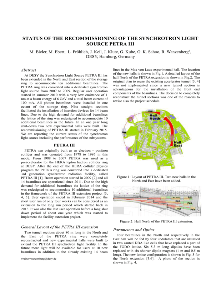
STATUS OF THE RECOMMISSIONING OF THE SYNCHROTRON LIGHT SOURCE PETRA III M. Bieler, M. Ebert, L. Fröhlich, J. Keil, J. Klute, G. Kube, G. K. Sahoo, R. Wanzenberg#, DESY, Hamburg, Germany Abstract At DESY the Synchrotron Light Source PETRA III has been extended in the North and East section of the storage ring to accommodate ten additional beamlines. The PETRA ring was converted into a dedicated synchrotron light source from 2007 to 2009. Regular user operation started in summer 2010 with a very low emittance of 1 nm at a beam energy of 6 GeV and a total beam current of 100 mA. All photon beamlines were installed in one octant of the storage ring. Nine straight sections facilitated the installation of insertion devices for 14 beam lines. Due to the high demand for additional beamlines the lattice of the ring was redesigned to accommodate 10 additional beamlines in the future. In an one year long shut-down two new experimental halls were built. The recommissioning of PETRA III started in February 2015. We are reporting the current status of the synchrotron light source including the performance of the subsystems. lines in the Max von Laue experimental hall. The location of the new halls is shown in Fig.1. A detailed layout of the hall North of the PETRA extension is shown in Fig.2. The original plan to reuse the existing accelerator tunnel [3, 4] was not implemented since a new tunnel section is advantageous for the installation of the front end components of the beamlines. The decision to completely reconstruct the tunnel sections was one of the reasons to revise also the project schedule. PETRA III PETRA was originally built as an electron – positron collider and was operated from 1978 to 1986 in this mode. From 1988 to 2007 PETRA was used as a preaccelerator for the HERA lepton hadron collider ring at DESY. After the end of the HERA collider physics program the PETRA ring was converted into a dedicated 3rd generation synchrotron radiation facility, called PETRA III [1]. Beam operation started in 2009 [2] and all 14 beamlines are operational since 2011. Due to the high demand for additional beamlines the lattice of the ring was redesigned to accommodate 10 additional beamlines in the framework of the PETRA III extension project [3, 4, 5]. User operation ended in February 2014 and the short user run of only four weeks can be considered as an extension to the long run period which started back in 2013. It was also the last user operation before a long shut down period of about one year which was started to implement the facility extension project. Figure 1: Layout of PETRA III. Two new halls in the North and East have been added. Figure 2: Hall North of the PETRA III extension. General Layout of the PETRA III extension Two tunnel sections about 80 m long in the North and the East of the PETRA ring were completely reconstructed and new experimental halls were built to extend the PETRA III synchrotron light facility. In the future more light will be available for users at 10 new beamlines in addition to the already existing 14 beam ____________________________________________ #rainer.wanzenberg@desy.de Parameters and Optics Four beamlines in the North and respectively in the East hall will be fed by four undulators that are installed in two canted DBA like cells that have replaced a part of the FODO lattice. Six 5.3 m long dipoles have been replaced with six shorter dipole magnets (1 m and 0.5 m long). The new lattice configuration is shown in Fig. 3 for the North extension [3,6]. A photo of the section is shown in Fig. 4. system for the new sections was developed along the lines set up for PETRA III [8, 9]. Short Chronology of the commissioning steps Figure 3: Optics of the PETRA III extension North. The lattice changes imply also a change in the synchrotron integrals I2 and I5 resulting in an emittance of 1.2 nm, which is 20 % larger than the previously achieved emittance of 1 nm [1]. The new design parameters are summarized in Table 1. The Northern straight section accommodates one of the damping wiggler arrays producing an extremely hard and powerful x-ray beam which will be utilized for materials science experiments. The Eastern long straight section is available for additional insertion devices. The optics has been modified to realize two straights of a length 5 m. Table 1: PETRA III (with Extension) design parameters Parameter PETRA III Energy / GeV 6 Circumference /m Emittance (horz. / vert.) /nm 2304 1.2 / 0.012 Total current / mA 100 Number of bunches 960 40 Bunch population / 1010 0.5 12 8 192 Bunch separation / ns In January and February 2015 last cabling work and the technical commissioning of the power supplies were completed. First turn steering started on Feb. 6 and ten days later it was possible to accumulate about 1 mA beam in the PETRA ring. During this early period of the recommissioning it was essential to identify a severe optics error due to a non-conformity in the electronics of the controller of a quadrupole power supply which resulted in an effective gradient error of 37 % due to a wrongly set magnet current which was not properly displayed in the control system. The transverse and longitudinal multi bunch feedback systems were quickly operational and it was possible to store higher beam currents after Feb. 18 which was also important to condition the vacuum system. At the end of February the new optics was carefully corrected based on orbit response measurements with all correctors. This achievement was impaired by problems with the control software which could finally be mitigated. The emittance diagnostic beamline [10] was quickly available and the measured horizontal emittance is in very good agreement with the design value from Table 1. The orbit feedback was extended to guarantee the required pointing stability of the particle beam [11]. The commissioning of the modified system with a new central control unit could be finished just in time in mid-March. The set-up of good conditions for the existing 14 beam lines started in parallel to the final commissioning steps. COMMISSIONING Goals and constrains One of the essential goals of the extension project was to minimize the idle time for the already existing 14 beam lines and to re-establish good conditions for user runs for these beamlines before the new beamlines are becoming operational step by step. Therefore the time to rebuild and recommission the machine was planned to be only one year. The shut-down started in Feb. 2014 and the recommissioning with beam started in Feb. 2015 on schedule. Care has been taken to minimize the effort for development of hardware components. For the magnets in the extension regions basically the same design as for PETRA III magnets [7] was used. Also the vacuum USER RUNS The user run with internal users started as scheduled on March 28 with 60 equally spaced bunches and total current of 80 mA. Since April 8 the total bunch current was 100 mA in 240 bunches and since April 22 100 mA in 960 bunches after improved vacuum conditions. Due to ion effects the vertical emittance is slightly larger than the design value when PETRA III is operated with 960 equally spaced bunches. But for the 60 and 240 bunch modes a vertical emittance close the design values was measured. Starting on April 27 external users were scheduled to do experiments at the 14 existing beamlines. Two of the new beamlines in the extension section North will be operational in autumn 2015. CONCLUSION The recommissioning of PETRA III after the implementation of the extension project was successfully finished on schedule. User operation started on March 28 for internal users and on April 27, 2015 for external users. Since March PETRA III is running with a total beam current of 100 mA. Figure 4: PETRA III extension North. The new DBA like lattice of the extension section North is shown in the photo from April 2015. The beam quality in the 960 bunch mode has not yet achieved the design values due to ion effects which are degrading the vertical emittance. ACKNOWLEDGMENT The authors would like to thank our collegue J.-L. Revol from the ESRF and our colleagues B. Beutner, P. Castro-Garcia, H. Ehrlichmann and M. Vogt from DESY for their help during the commissioning of PETRA III. Thanks goes to our colleagues from the DESY groups MCS, MDI, MEA, MHF-e, MIN, MKK, MSK, MVS which are responsible for the successful installation and commissioning of the essential technical subsystems of PETRA III. We thank also the project leader W. Drube for the good and constructive co-operation. Last but not least we thank A. Kling for his enthusiasm and efforts in developing the DBA like lattice for the new extension sections. REFERENCES [1] Editors: K. Balewski, W. Brefeld, W. Decking, H. Franz, R. Röhlsberger, E. Weckert, “PETRA III: A low Emittance Synchrotron Radiation Source”, DESY 2004-035, February 2004. [2] K. Balewski, “Commissioning of PETRA III”, IPAC’10, Kyoto, Japan (2010). [3] K. Balewski et al., “PETRA III Upgrade”, IPAC’11, San Sebastian, Spain (2011). [4] M. Bieler et al., “Status of the PETRA III Upgrade”, IPAC’12, New Orleans, Louisiana, USA (2012). [5] Extension project: http://petra3-extension.desy.de [6] A. Kling, design of the PETRA III extension lattice, private communication. [7] E. Bondarchuk et al., “Magnets for the PETRA III Project”, IEEE Transaction on Applied Superconductivity Vol. 16, no.2, p. 220-223, 2006. [8] M. Seidel et al., “The Vacuum System for PETRA III”, PAC ‘05, Knoxville, USA (2005). [9] R. Böspflug et al., “Vacuum system design of the third generation synchrotron radiation source PETRA III”, J. Phys. Conf. Ser. 100, 092012 (2008). [10] G. Kube et al., “PETRA III Diagnostics Beamline for Emittance Measurements”, IPAC ‘10, Kyoto, Japan (2010). [11] J. Klute et al., “The PETRA III Fast Orbit Feedback System”, DIPAC ‘11, Hamburg, Germany (2011).

