Lab 7
advertisement
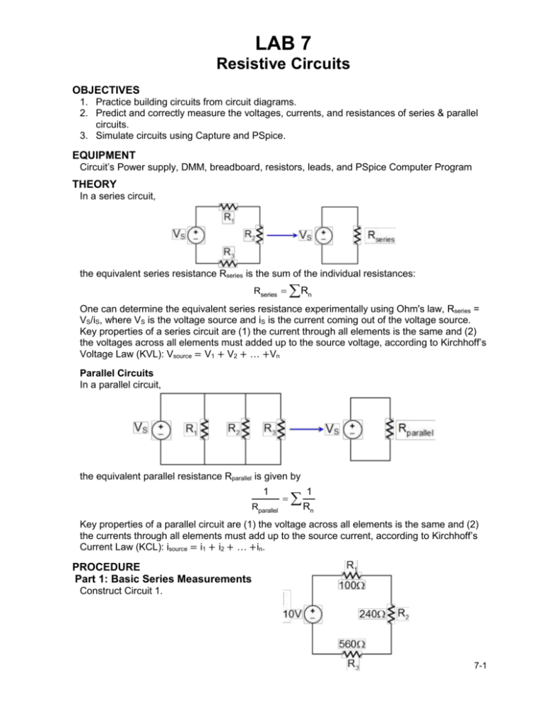
LAB 7 Resistive Circuits OBJECTIVES 1. Practice building circuits from circuit diagrams. 2. Predict and correctly measure the voltages, currents, and resistances of series & parallel circuits. 3. Simulate circuits using Capture and PSpice. EQUIPMENT Circuit’s Power supply, DMM, breadboard, resistors, leads, and PSpice Computer Program THEORY In a series circuit, the equivalent series resistance Rseries is the sum of the individual resistances: Rseries Rn One can determine the equivalent series resistance experimentally using Ohm's law, Rseries = VS/iS, where VS is the voltage source and iS is the current coming out of the voltage source. Key properties of a series circuit are (1) the current through all elements is the same and (2) the voltages across all elements must added up to the source voltage, according to Kirchhoff’s Voltage Law (KVL): Vsource = V1 + V2 + … +Vn Parallel Circuits In a parallel circuit, the equivalent parallel resistance Rparallel is given by 1 Rparallel 1 Rn Key properties of a parallel circuit are (1) the voltage across all elements is the same and (2) the currents through all elements must add up to the source current, according to Kirchhoff’s Current Law (KCL): isource = i1 + i2 + … +in. PROCEDURE Part 1: Basic Series Measurements Construct Circuit 1. 7-1 Part 1A: Equivalent Series Resistance a. Predict the equivalent series resistance RS,thy using the measured resistor values. b. Measure the total resistance RS,expt using an ohmmeter. Compare the predicted and the measured using a percent difference. How do they compare? Ohm’s Law Method of Determining Equivalent Resistance c. Measure the current (after energizing Circuit 1) using an ammeter (remember to “break the circuit”). d. Predict the equivalent resistance using Ohm’s law RS,ohm = VS/iS. e. Compare the predicted and the measured using a percent difference. How do they compare? Can the 3 series resistors be replaced with the equivalent series resistance Rseries? Explain your answer. Part 1B: Properties of a Series Circuit Series Voltage a. Predict the voltages (V1, V2, V3)thy across each resistor using the Voltage Divider Rule (VDR). b. Measure the voltages (V1, V2, V3)expt across each resistor. Compare the predicted and the measured using a percent difference. How do they compare? Record your values in table. c. Verify that Kirchhoff’s Voltage law is satisfied around the path (VS = V1 + V2 + V3)? From your data table how does the voltage depend on the resistance? Explain your reasoning. Series Current d. Measure the current before each three resistors by inserting the DMM in series with each resistor. Record your values. Compare the three currents; what can you deduce about the current in a series circuit? Explain your reasoning. Part 2 Basic Parallel Measurements Construct Circuit 2. Part 2A: Equivalent Parallel Resistance a. Predict the equivalent parallel resistance RP,thy using measured resistor values. b. Measure the equivalent parallel resistance RP,expt using a DMM. Compare the predicted and the measured using a percent difference. How do they compare? How does the equivalent parallel resistance compare with that of the individual resistor values? Explain your answer. Ohm’s Law Method of Determining Equivalent Resistance c. Measure the source current (after energizing Circuit 2) using an ammeter (remember to “break the circuit”). d. Predict the equivalent resistance using Ohm’s law RP,ohm = VS/iS. e. Compare the predicted and the measured using a percent difference. How do they compare? Can the 3 parallel resistors be replaced with the equivalent parallel resistance Rparallel? Explain your answer. Part 2B: Properties of a Parallel Circuit Parallel Currents a. Predict the currents (i1, i2, i3)thy through each resistor using the Current Divider Rule (CDR). 7-2 b. Measure the currents (i1, i2, i3)expt through each resistor with the DMM. Compare the predicted and the measured using a percent difference. How do they compare? Record your values in table. c. Verify that Kirchhoff’s Current law is satisfied at the top node (iS = i1 + i2 + i3)? From your data table how does the current depend on the resistance? Explain your reasoning. Parallel Voltages d. Measure the voltage across each three resistor using a DMM. Compare the three voltages – what can you deduce about the voltage in a parallel circuit? Explain your reasoning. Part 3: PSpice Circuit Simulation Program For circuits-3, -4 and -5, continue using R1 = 100Ω, R2 = 240Ω, and R3 = 560Ω. a. Construct Circuit-3. b. Use Capture to draw a schematic and simulate Circuit-3 using measured resistor values. c. Measure the current and voltage of each resistor with the DMM. d. Compare the PSpice and measured voltages and currents for Circuit-3. How do the results compare? Summarize all of the data in table and include a copy of the schematic with your lab report. e. Repeat parts (3a-3c) for Circuit-4. f. Repeat parts (3a-3c) for Circuit-5 7-3


