Lab 5
advertisement
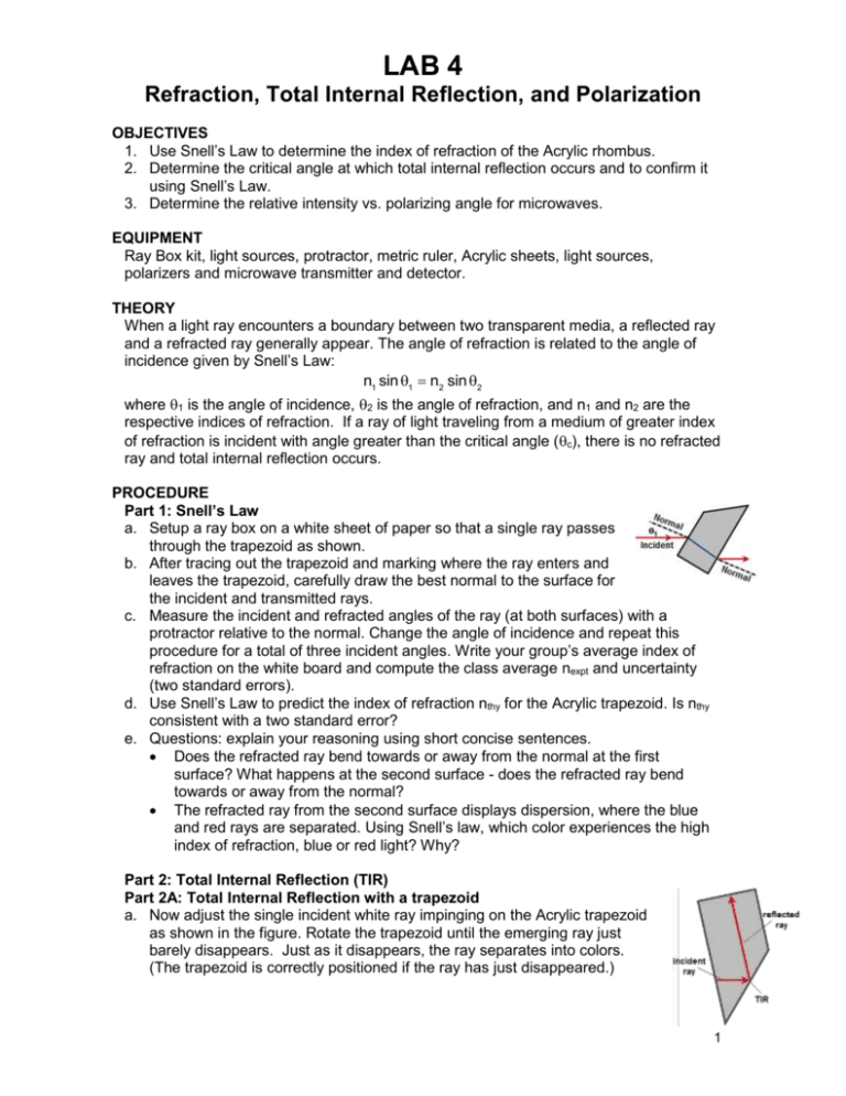
LAB 4 Refraction, Total Internal Reflection, and Polarization OBJECTIVES 1. Use Snell’s Law to determine the index of refraction of the Acrylic rhombus. 2. Determine the critical angle at which total internal reflection occurs and to confirm it using Snell’s Law. 3. Determine the relative intensity vs. polarizing angle for microwaves. EQUIPMENT Ray Box kit, light sources, protractor, metric ruler, Acrylic sheets, light sources, polarizers and microwave transmitter and detector. THEORY When a light ray encounters a boundary between two transparent media, a reflected ray and a refracted ray generally appear. The angle of refraction is related to the angle of incidence given by Snell’s Law: n1 sin 1 n2 sin 2 where 1 is the angle of incidence, 2 is the angle of refraction, and n1 and n2 are the respective indices of refraction. If a ray of light traveling from a medium of greater index of refraction is incident with angle greater than the critical angle (c), there is no refracted ray and total internal reflection occurs. PROCEDURE Part 1: Snell’s Law a. Setup a ray box on a white sheet of paper so that a single ray passes through the trapezoid as shown. b. After tracing out the trapezoid and marking where the ray enters and leaves the trapezoid, carefully draw the best normal to the surface for the incident and transmitted rays. c. Measure the incident and refracted angles of the ray (at both surfaces) with a protractor relative to the normal. Change the angle of incidence and repeat this procedure for a total of three incident angles. Write your group’s average index of refraction on the white board and compute the class average nexpt and uncertainty (two standard errors). d. Use Snell’s Law to predict the index of refraction nthy for the Acrylic trapezoid. Is nthy consistent with a two standard error? e. Questions: explain your reasoning using short concise sentences. Does the refracted ray bend towards or away from the normal at the first surface? What happens at the second surface - does the refracted ray bend towards or away from the normal? The refracted ray from the second surface displays dispersion, where the blue and red rays are separated. Using Snell’s law, which color experiences the high index of refraction, blue or red light? Why? Part 2: Total Internal Reflection (TIR) Part 2A: Total Internal Reflection with a trapezoid a. Now adjust the single incident white ray impinging on the Acrylic trapezoid as shown in the figure. Rotate the trapezoid until the emerging ray just barely disappears. Just as it disappears, the ray separates into colors. (The trapezoid is correctly positioned if the ray has just disappeared.) 1 b. Trace the surfaces of the trapezoid, the exactly the point where the ray is internally reflected, and incident and reflected rays. c. Draw the incident and reflected rays after you remove the trapezoid. From these two rays, measure the critical angle (c)expt,1. d. Calculate the critical angle (c)thy using Snell’s law and the index of refraction for the Acrylic you measured in Part 1. Calculate a percent difference between the measured and theoretical values. How do they compare? e. How does the brightness of the internally reflected ray change when the incident angle changes from less than c to greater than c? Part 2B: Total Internal Reflection with Acrylic Sheets a. Place an Acrylic sheet with the paper side down on the lab bench. Shine a laser directly above and perpendicular onto the Acrylic sheet so that it produces a circle. b. Using the radius of the circle, the thickness of the Acrylic sheet, and the index of refraction from Part (1), determine the critical angle (c)expt,2 for the Acrylic sheet. c. Repeat part (b) for various thicknesses of Acrylic sheets. Average and organize your data into a single data table. Calculate a percent difference between the measured and theoretical values. How do they compare? d. Explain why the inside of the circle is dark compared to the outside of the circle. Part 3: Polarization Microwave Polarization a. A microwave transmitter emits polarized microwaves and is detected by a microwave detector. Setup the transmitter, polarizing grating and detector as shown on the right. b. Measure the relative intensity as the angle θ of the polarizing grating is rotated from 0o to 180o. Organize your data into a table. Plot the relative intensity verses the polarizing angle θ. Explain your plot. Optical Polarization c. Using a light source and an optical polarizer, shine light off of glass and rotate the polarizer similar to part (b). Is the light reflected from the glass polarizer? Explain your reasoning. Roughly plot the intensity verses angle of the polarizer. Is this similar to that measure in Part (3A)? Explain your reasoning. 2
