simple machine lab form B
advertisement
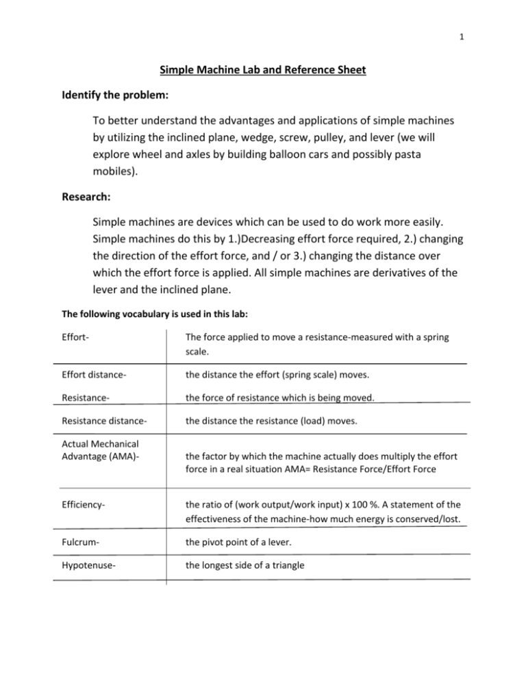
1 Simple Machine Lab and Reference Sheet Identify the problem: To better understand the advantages and applications of simple machines by utilizing the inclined plane, wedge, screw, pulley, and lever (we will explore wheel and axles by building balloon cars and possibly pasta mobiles). Research: Simple machines are devices which can be used to do work more easily. Simple machines do this by 1.)Decreasing effort force required, 2.) changing the direction of the effort force, and / or 3.) changing the distance over which the effort force is applied. All simple machines are derivatives of the lever and the inclined plane. The following vocabulary is used in this lab: Effort- The force applied to move a resistance-measured with a spring scale. Effort distance- the distance the effort (spring scale) moves. Resistance- the force of resistance which is being moved. Resistance distance- the distance the resistance (load) moves. Actual Mechanical Advantage (AMA)- the factor by which the machine actually does multiply the effort force in a real situation AMA= Resistance Force/Effort Force Efficiency- the ratio of (work output/work input) x 100 %. A statement of the effectiveness of the machine-how much energy is conserved/lost. Fulcrum- the pivot point of a lever. Hypotenuse- the longest side of a triangle 2 Equations: Work input=Effort Force x Effort Distance Work output= Resistance Force x Resistance Distance AMA= Resistance Force/Effort Force Efficiency= (work output/work input) x 100 % Hypothesis: What advantages is there in using the simple machines? ___________________________________________________________________ ___________________________________________________________________ ___________________________________________________________________ Materials : (these are already set up around the room) Meterstick Pulleys Spring Scale 1 kg masses String Scissors Marker/piece of Block of wood paper Screwdriver/screws Fulcrums/hangers Protractor Ramp/board 3 Part 1: Inclined Planes (Caution: Heavy weight used)s Inclined planes are flat, slanted surfaces that multiply force. They are a type of simple machine that a resistance (a weighted object) is moved on. Procedures: 1. 2. 3. 4. Measure the angle of the inclined plane using a protractor. Place the 1 kg mass at the bottom of the inclined plane. Pull the mass up the incline using the spring scale-noting the force required. Measure the distance to the top of the incline up the ramp. Measure the height. Record. 5. Vertically lift the mass from the desk to the top of the incline-record the force required. 6. Complete the data table below and do calculations. 7. Repeat the procedure. Data: Trial Angle 1. 2. Height (Rdist) Length (Edist) Effort Force Resistance Force 4 Data Calculations Trial Angle Work Input Work Output AMA Efficiency Analysis: 1. How did the efficiency compare between the angles of the incline? Explain. ___________________________________________________________ ___________________________________________________________ ___________________________________________________________ ___________________________________________________________ Conclusion If you want to build an incline plane that requires the least amount of force to push something up, how would you build it? Why? ___________________________________________________________ ___________________________________________________________ ___________________________________________________________ ___________________________________________________________ ___________________________________________________________ 5 Part 2 Wedges Wedges are usually shaped like two small inclined planes glued together. They are simple machines that move a resistance. They usually have a “cutting” or “splitting” ability. Procedure: 1. Measure the width of the wedge and the length of the wedge and record in the data table. 2. Calculate the Ideal Mechanical Advantage of each wedge. Data: Wedge Angle Width (Rdist) Length (Edist) Analysis: 1. Which wedge required the least force to separate the blocks? ___________________ IMA 6 2. Is it better to have a long thin wedge or a short and wide wedge if you want to cut thought something easily? Why? _____________________________________________________________ _____________________________________________________________ _____________________________________________________________ 3. Why do sharp knives cut better than dull knives? _____________________________________________________________ _____________________________________________________________ _____________________________________________________________ _____________________________________________________________ 4. List some items that are made of wedges. (need all 5) 1. ___________________ 2. ___________________ 3. ___________________ 4. ___________________ 5. ___________________ 7 Part 3 Screws (CAUTION: Sharp edges and sharp wood pieces) Screws are inclined planes wrapped around a cylinder. They’re like twisted wedges. They, too, are simple machines that move a resistance. Procedure: 1. Cut an 8.5” x 11” pieces of paper in half diagonally to make a paper inclined plane. 2. Darken or color the hypotenuse edge with a marker. 3. Place a pencil inside the parallel to the shortest side, with the marker edge facing out. 4. Roll the pencil so that the paper wraps around it. Describe what you see. _____________________________________________________________ _____________________________________________________________ _____________________________________________________________ 5. Take the block of wood. Take the screw with the least number of threads per area and use the screwdriver to screw it into the wood. 6. Screw the other screws in and compare how difficult it is to screw in those with more threads versus those with less threads. Compare in the table below. 8 Data: Threads Description of Difficulty Few Many Analysis: Which screws were more difficult to screw in?_____________________________ Conclusion: 1. If you had very dense wood, would you use screws with more or less threads per area? Why? ________________________________________________________________ ________________________________________________________________ ________________________________________________________________ 2. If you had to mount something heavy to the wall, which screws would you use? Why? ________________________________________________________________ ________________________________________________________________ ________________________________________________________________ ________________________________________________________________ 9 Part 4: Lever (Caution: Heavy weight used) A lever is a rigid bar that rotates about a fixed point. Procedure: 1. Review the classes of levers, and sketch a first, second and third class lever below. First Class Second Class Third Class 2. Build an lst class lever using the meter sticks and clamps. Locate the fulcrum 30 cm from one end of the meter stick. 3. Hang a 1 kg mass on the short end of the meter stick. 4. Use your spring scale to pull down on the long end of the lever noting both the force required and the actual distance you pulled the lever down. Also note how far the resistance was lifted in process. 5. Fill in the data chart below and do the calculation chart. 6. Repeat the experiment using a 2nd class lever-putting the fulcrum at the end of the meter stick and hanging the 1 kg mass 40 cm from the fulcrum. Place the spring scale at the far end of the meter stick (opposite the fulcrum). 7. Repeat the experiment using a 3rd class lever-just switch the location of the 1 kg mass and the spring scale. 10 8. Data Table: Type of Effort Distance lever 1st Resistance Distance Effort Force Resistance Force 2nd 3rd Data calculations: Use provided terms on reference sheet. Type of lever Work Input Work Output AMA Efficiency 1st 2nd 3rd Analysis: 1. Compare and contrast the efficiency of each class lever. Which is the most efficient? Why? _____________________________________________________________ _____________________________________________________________ _____________________________________________________________ _____________________________________________________________ _____________________________________________________________ 11 2. What is the advantage of using each class lever? What is the disadvantage of each? Class levers Advantages Disadvantages 1st 2nd 3rd 3. What did Archimedes mean when he said, “give me a lever long enough and I can move the world.” Be specific. _____________________________________________________________ _____________________________________________________________ _____________________________________________________________ _____________________________________________________________ _____________________________________________________________ 12 Part 5 Pulleys: (Caution: Heavy weight used) A pulley is a simple machine made of a grooved wheel with a rope or cable wrapped around it. 1. Draw and label the following pulley systems. Fixed Movable Block and Tackle 1. Build a fixed pulley system using a 1 kg mass as resistance. 2. Lift the 1 kg mass using the spring scale to pull with. Record the effort distance, resistance distance, effort force and resistance force in the data table for the fixed pulley. 3. Repeat the above steps using a moveable pulley and a block and tackle pulley system. Data Table: Type of Pulley Fixed Moveable Block and Tackle Effort Distance Resistance Distance Effort Force Resistance Force 13 Data calculations: Use provided terms on reference sheet. Type of Pulley Fixed Work Input Work Output AMA Efficiency Moveable Block and Tackle Analysis Questions: 1. How does the number of supporting ropes relate to the mechanical advantage of each pulley system? _____________________________________________________________ _____________________________________________________________ _____________________________________________________________ 2. What advantages can be achieved by using a pulley system? How can work be made easier by using pulleys? _____________________________________________________________ _____________________________________________________________ _____________________________________________________________ _____________________________________________________________ 14 Part 6 Wheel and Axle A wheel and axle is a machine made of two circular or cylindrical objects that are fastened together and that rotate about a common axis. 1. Draw an example of a wheel and axle. Label. 2. How is ideal mechanical advantage of a wheel and axle calculated? ___________________________________________________________________ ___________________________________________________________________ ___________________________________________________________________ ___________________________________________________________________
