Total Internal Reflection
advertisement
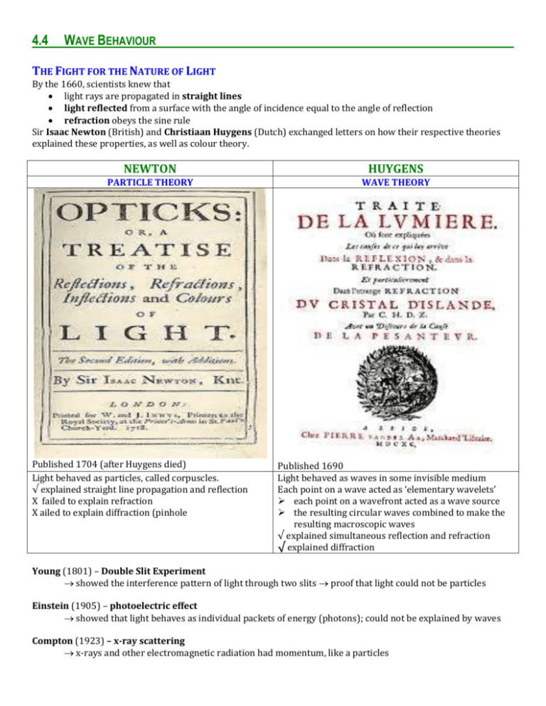
4.4 WAVE BEHAVIOUR THE FIGHT FOR THE NATURE OF LIGHT By the 1660, scientists knew that light rays are propagated in straight lines light reflected from a surface with the angle of incidence equal to the angle of reflection refraction obeys the sine rule Sir Isaac Newton (British) and Christiaan Huygens (Dutch) exchanged letters on how their respective theories explained these properties, as well as colour theory. NEWTON HUYGENS PARTICLE THEORY WAVE THEORY Published 1704 (after Huygens died) Light behaved as particles, called corpuscles. √ explained straight line propagation and reflection X failed to explain refraction X ailed to explain diffraction (pinhole Published 1690 Light behaved as waves in some invisible medium Each point on a wave acted as ‘elementary wavelets’ each point on a wavefront acted as a wave source the resulting circular waves combined to make the resulting macroscopic waves √ explained simultaneous reflection and refraction √ explained diffraction Young (1801) – Double Slit Experiment showed the interference pattern of light through two slits proof that light could not be particles Einstein (1905) – photoelectric effect showed that light behaves as individual packets of energy (photons); could not be explained by waves Compton (1923) – x-ray scattering x-rays and other electromagnetic radiation had momentum, like a particles REFLECTION AND REFRACTION OF WAVES Reflection When a wave strikes a boundary between two different media, some energy is transferred to the new medium (refraction) some energy is reflected in the original medium. For all waves pulses (both transverse and longitudinal), the transmitted pulse always has the same phase as the original wave. The phase of the reflected pulse depends on the type of wave and the type of transition. WAVE TYPE LIGHT (FAST) TO HEAVY (SLOW) HEAVY (SLOW) TO LIGHT (FAST) ropes, strings, water TRANSVERSE string to rope → opposite phase (inverted) rope to string → same phase (upright) LONGITUDINAL same phase (upright) opposite phase (inverted) sound, compressed springs Reflection of waves striking a barrier at an angle – Law of Reflection For ALL waves (transverse / longitudinal and mechanical waves / electromagnetic waves): the angle of incidence, i, is equal to the angle of refraction, r. Both angles are measured relative to the normal. Normal imaginary line constructed perpendicular to the surface where the wave ray strikes a barrier i=r The diagram shows a straight wavefront just before and just after it reflects from a straight barrier. The angle of incidence is between the direction of propagation and the normal. The angle of incidence is shown to be equal to the angle between the incident wavefront and the barrier. Similarly for the angle of reflection, the reflected wavefront and the barrier. reflected wavefront i 90-i i incident wavefront 90-r r r Refraction and Snell’s Law A wave is refracted when it is transmitted from one medium to another medium the wave speed, v changes the wavelength, λ changes the frequency, f of the wave remains the same (only the wave source affects the frequency) The direction of the wave ray will change when the incident wave does not strike the barrier normally (90°). In the slower medium, the wavelength is shorter. In the faster medium, the wavelength is longer, Consider the universal wave equation: v = f v For all media, the frequency remains constant. Index of Refraction, n Every substance has a distinctive index of refraction. The index of refraction is the ratio of the speed of light in a vacuum, c, to the speed of light in the medium, v. n substance index of refraction, n vacuum exactly 1 c v air 1.0008 water 1.333 glass 1.54 diamond 2.42 Snell’s Law compares angles of light in the two media; the direction of the light does not matter. n1 sinθ1= n2sinθ2 Worked Example For air (nA=1.0003) and water (nW=1.333), the angle of the light in air is 60°. Find the angle of the light in water nA sin A nW n 1.00 W sin 1 A sin A sin 1 sin 60 sin 10.651... 40.628... 1.33 nW nA sin A nW sin W sin W Dispersion of white light The refractive index depends slightly on the wavelength of the light. Different wavelengths are refracted at different angles. This results in the dispersion of colours (rainbow) produced by white light that passes through a prism or water droplets. Total Internal Reflection Total internal reflection occurs when light travelling in an optically dense medium strikes a barrier at an angle greater than the critical angle, resulting in no light being refracted and all of the light energy being reflected. Critical Angle the angle in the optically dense medium (higher index of refraction) that produces an angle of 90° in the other so that light does not escape the more optically dense medium. Worked Example For water (1) and air (2) 1.333 sin θc = 1.0003 sin(90°) 1.0003 sin 90 48.6 1.333 water sin 1 This means that if you are in the water and shine a light toward the surface, if the angle relative to the normal is greater than 48.6º, then all of the light will be reflected back into the water (no light escapes!) Uses of total internal reflection include: optical fibres for transmission of digital signals refraction telescopes Diffraction Diffraction the spreading of a wave as it goes past an obstacle or through an aperture (opening). Diffraction occurs when the wavelength is comparable to or larger than the size of the obstacle or aperture. Visible light has a short wavelength (500 nm), it is only diffracted when the opening is very small. The medium is the same so the wave speed and wavelength stays constant. Larger wavelengths are diffracted more and have less of a shadow effect. Double-source interference When two waves at the same point in space, an interference pattern is produced. All waves and only waves produce interference patterns. Path Difference, ∆r the difference in distance of a point from the two sources Maximum Constructive Interference – maximum resultant displacement where two crests or two troughs meet. The two waves are ‘in phase’ at that point. ∆r = n Total Destructive Interference – no displacement where waves of opposite phase but equal value meet Opposite phase means there is a phase difference of half of a wavelength (½ ) ∆r = (n+ ½) At Point Z, crests from each source meet. x1 = 3 and x2 = 4 ∆r = 1 For any point where two crests meet, the path difference will always be a whole number multiple of the wavelength, At Point W, a crest from S2 meets a trough from S1. The path length from S1 = 3.5 and from S2 = 5 ∆r = 1.5 Double-slit Interference Thomas Young first demonstrated interference of light through two slits in 1901. This provided irritable evidence of light behaving as a wave and not as a particle, contrary to Newton’s corpuscular theory. The relationships between path difference and points of constructive and destructive interference are same as for double-source interference. For IB, d = distance between slits D = distance from slits to the screen s = ‘fringe spacing’ = distance on the screen between the centre of the central maximum and the centre of an adjacent local maximum (denoted as y in the diagram above. From this: s D d
