Temperature dependence of different
resistors and diodes with Cobra4
TEP
Related topics
Carbon film resistor, metallic film resistor, PTC, NTC, Z diode, avalanche effect, Zener effect, charge
carrier generation, free path, Matthiessen’s rule.
Principle
The temperature dependence of an electrical parameter (e.g. resistance, conducting-state voltage,
blocking voltage) of different components is determined. To do this, the immersion probe set is immersed in a water bath and these parameters are measured at different well defined temperatures.
Equipment
1
1
1
1
1
1
1
2
2
Immersion probes f. determining ct
Immersion thermostat Alpha A, 230V
Bath for thermostat, Makrolon
External circulation set f. thermostat
Alpha A
PEK carbon resistor 1 W 5% 2,2
kOhm
Connection box
Connecting cord, l = 500 mm, blue
Connecting cord, l = 750 mm, red
Connecting cord, l = 750 mm, blue
07163-00
08493-93
08487-02
1
2
1
08492-01
1
39104-23
1
06030-23
07361-04
07362-01
07362-04
1
Cobra4 Wireless Manager
Cobra4 Wireless-Link
Cobra4 Sensor-Unit Energy
Digital Function Generator, USB,
incl. Cobra4 Software
Cobra4 Sensor-Unit Temperature,
semiconductor -20...110 °C
Additionally required
PC with USB interface, Windows XP
or higher
12600-00
12601-00
12656-00
13654-99
12640-00
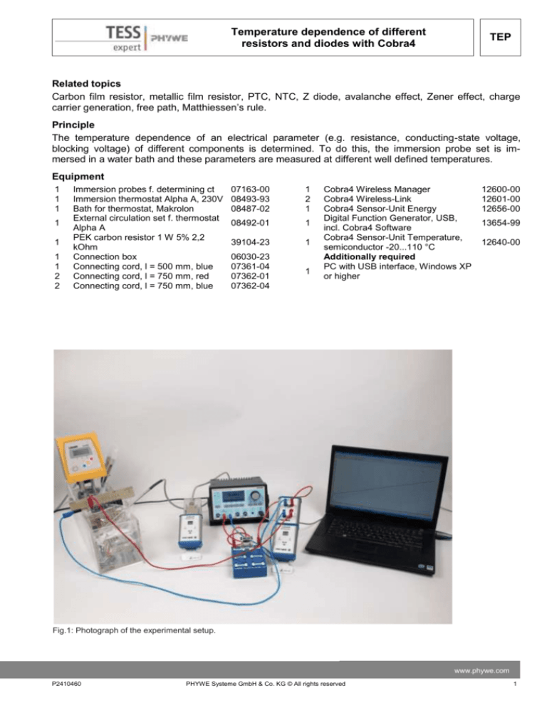
Fig.1: Photograph of the experimental setup.
www.phywe.com
P2410460
PHYWE Systeme GmbH & Co. KG © All rights reserved
1
TEP
Temperature dependence of different
resistors and diodes with Cobra4
Tasks
1. Measurement of the temperature dependence of the resistance of different electrical components.
2. Measurement of the temperature dependence of the conducting state voltage of semiconducting diodes.
3. Measurement of the temperature dependence of the voltage in the Zener diode and the avalanche
effects.
Set-up and Procedure
Set up the equipment as seen in Fig. 1. The immersion probe set has to be put into a watertight plastic
bag – be sure the immersion probe set does not get wet and there is no leakage – and put the temperature sensor right into that bag, too. Be careful not to destroy the coils by scratching etc. Be sure to connect the hose for the water coming from the circulation pump properly so that the water is led back into
the bath before turning on the thermostat. Fill the bath with enough water that the probes are under the
water surface. Set the temperature control on the thermostat to the reference temperature of 20°C and
turn it on. Connect the Digital Function Generator and the wireless manager to a USB port. Connect the
single socket of the immersion probe set to the blue socket of the Sensor-Unit Energy. Be sure to insert
the 2.2 kOhm resistor in the circuit between the Sensor-Unit and the function generator. Connect the
Cobra4 Wireless Manager to a USB port of the computer, plug the Cobra4 Sensor-Electricity on the Cobra4 Wireless-Link and connect the Digital Function Generator to another USB port.
Start the “measure” program on your computer and load the “Second order conductors” experiment.
(Experiment > Open experiment). All pre-settings that are necessary for measured value recording are
now carried out.
When the temperature of the water bath has
become constant, plug the cable coming from
the red socket of the SU-Energy in the first
socket of the probe set and click on
in the
icon strip to start measurement. Go to the next
socket and record a measurement again – one
for each socket and the same temperature.
Then raise the temperature of the water bath
by 10 °C (or 15 °C for a faster performance).
While the temperature is reaching the desired
value, use "Measurement" > "Enter data manually" to note down the interesting values:
Create a measurement with 10 channels (see
Fig. 2) and enter there the resistance values in
case of the carbon resistor, the metal film resistor, the PTC and NTC resistors, the copper
and CuNi wires and the diodes. After typing
the values, confirm them with "return". Evaluate the resistance with the "Regression" function in the measured curves: The resistance is
the inverse slope. For the Si and Ge diodes
take down the forward voltage where the current exceeds 1 mA and for the Zener diodes
take down the breakthrouh voltage, where the
current exceeds 1 mA, using the "Survey"
function of "measure". Repeat the procedure
for the next temperature steps until 85 °C taking all the data down into the same "Manually
created measurement".
2
Fig. 2: Manually created measurement.
PHYWE Systeme GmbH & Co. KG © All rights reserved
P2410460
Temperature dependence of different
resistors and diodes with Cobra4
TEP
Theory and evaluation
In restricted temperature ranges the change in the resistance of the electrical components with temperature can be assumed to be linear. In these regions, a general formula for the dependence of the resistance on the temperature is valid:
R(T) = Rref + Rref · α · (T – Tref)
where
R(T) = Resistance at temperature T
Rref = Resistance at Tref (usually 20°C)
α = Temperature coefficient
T = Temperature at time of measurement
Tref = Reference temperature (usually 20°C)
You may split the curves from your "Manually created measurement" up into several diagrams using
"Measurement" > "Channel manager…". Figs. 3 to 6 show measurement results.
Fig. 3: Resistance of different materials vs. temperature.
The measurement yields a temperature coefficient for copper of
The other temperature coefficients are not to be discriminated from zero with the here achieved level of
precision. In copper wire the free path of the electrons in the electron vapour, which contribute to charge
transport, becomes shorter with increasing temperature. The change in resistance can be seen: the resistance increases. The result is a positive temperature coefficient. The liteature value (Giancoli, Douglas C., Physics, 4th Ed., Prentice Hall, 1995) for copper is
The two NTC and PTC resistors consist of alloys. Depending on their compositions, great changes in resistance can be realised in a small temperature range. The curves that are recorded in this experiment
can not be considered linear. They serve to illustrate the behaviour of NTC and PTC resistors.
www.phywe.com
P2410460
PHYWE Systeme GmbH & Co. KG © All rights reserved
3
TEP
Temperature dependence of different
resistors and diodes with Cobra4
Fig. 4: Resistance of NTC and PTC elements vs. temperature.
Fig. 5: Forward voltage of diodes in dependence on temperature.
In semiconductors (Fig. 10) the number of charge carriers and the charge carrier density increases with
temperature (charge carrier generation, electron-hole pair formation). From the law
where
= Intrinsic conductivity
e = Elementary charge
n = Charge carrier density
μ = Mobility
one can see that the intrinsic conductivity of the semiconductor thus increases. The mobility indeed decreases with increasing temperature, but the increase in the charge carrier densityovercompensates for
4
PHYWE Systeme GmbH & Co. KG © All rights reserved
P2410460
Temperature dependence of different
resistors and diodes with Cobra4
TEP
this effect.
Fig. 6: Breakdown voltage vs. temperature.
At low voltages, around 3 V, a Zener breakdown occurs in Z diodes. As a result of the strong electric
field, electron-hole pairs are spontaneously generated in the inner electron shells in the barrier-layer
zone. Under the influence of the field, they cross the barrier layer. A higher temperature increases the
energy of the bound charge carriers. As a consequence, the Zener effect can occur at lower voltages. In
the avalanche effect, the charge carriers are accelerated by the electric field to such a great degree that
they in turn ionize other atoms on their way producing more carriers, that can be accelerated. The higher
temperature shortens the free path, so that for releasing the same amount of charge carriers, the voltage
must increase with the temperature.
The following values are read from Fig. 11:
αZPD 2.7 = -7.9 · 10-4 /K
αZPD 6.8 = +4.4 · 10-4 /K
Literature values:
αZPD 2.7 = -9…-4 · 10-4 /K
αZPD 6.8 = +2…+7 · 10-4 /K
with α the relative temperature coefficient.
www.phywe.com
P2410460
PHYWE Systeme GmbH & Co. KG © All rights reserved
5
TEP
Temperature dependence of different
resistors and diodes with Cobra4
Room for notes:
6
PHYWE Systeme GmbH & Co. KG © All rights reserved
P2410460


