AMS, 2012
advertisement
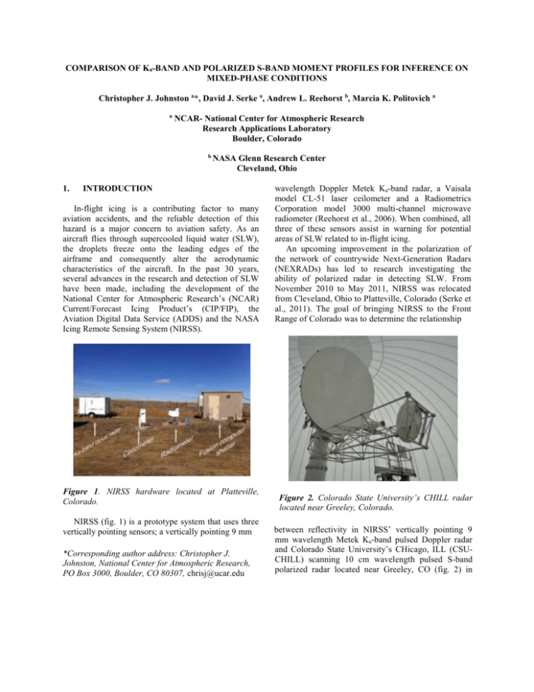
COMPARISON OF Ka-BAND AND POLARIZED S-BAND MOMENT PROFILES FOR INFERENCE ON MIXED-PHASE CONDITIONS Christopher J. Johnston a*, David J. Serke a, Andrew L. Reehorst b, Marcia K. Politovich a a NCAR- National Center for Atmospheric Research Research Applications Laboratory Boulder, Colorado b 1. NASA Glenn Research Center Cleveland, Ohio INTRODUCTION In-flight icing is a contributing factor to many aviation accidents, and the reliable detection of this hazard is a major concern to aviation safety. As an aircraft flies through supercooled liquid water (SLW), the droplets freeze onto the leading edges of the airframe and consequently alter the aerodynamic characteristics of the aircraft. In the past 30 years, several advances in the research and detection of SLW have been made, including the development of the National Center for Atmospheric Research’s (NCAR) Current/Forecast Icing Product’s (CIP/FIP), the Aviation Digital Data Service (ADDS) and the NASA Icing Remote Sensing System (NIRSS). Figure 1. NIRSS hardware located at Platteville, Colorado. NIRSS (fig. 1) is a prototype system that uses three vertically pointing sensors; a vertically pointing 9 mm *Corresponding author address: Christopher J. Johnston, National Center for Atmospheric Research, PO Box 3000, Boulder, CO 80307, chrisj@ucar.edu wavelength Doppler Metek Ka-band radar, a Vaisala model CL-51 laser ceilometer and a Radiometrics Corporation model 3000 multi-channel microwave radiometer (Reehorst et al., 2006). When combined, all three of these sensors assist in warning for potential areas of SLW related to in-flight icing. An upcoming improvement in the polarization of the network of countrywide Next-Generation Radars (NEXRADs) has led to research investigating the ability of polarized radar in detecting SLW. From November 2010 to May 2011, NIRSS was relocated from Cleveland, Ohio to Platteville, Colorado (Serke et al., 2011). The goal of bringing NIRSS to the Front Range of Colorado was to determine the relationship Figure 2. Colorado State University’s CHILL radar located near Greeley, Colorado. between reflectivity in NIRSS’ vertically pointing 9 mm wavelength Metek Ka-band pulsed Doppler radar and Colorado State University’s CHicago, ILL (CSUCHILL) scanning 10 cm wavelength pulsed S-band polarized radar located near Greeley, CO (fig. 2) in scenarios of known in-flight icing conditions. NIRSS was located south of CSU-CHILL at an azimuth of ~195° at a range of 30 km, in an unblocked section of the radar scan range. The purpose of this work was to determine the practicality of using only S and/or K a reflectivity profiles in icing and non-icing cases. atmospheric water vapor and temperature profiles (Solheim et al., 1998). This information is ingested into NIRSS’ fusion algorithm which then allows the system to detect the location of subfreezing layers and the existence of SLW. For this study, the absorption of liquid water found from the DWR was compared to the ILW output of the radiometer. 2. BACKGROUND 2.2 2.1 Review of Error Sources Radar Methodology Previous research (Ellis and Vivekanandan, 2011) shows that the difference in reflectivity (dB) of collocated, matched beamed radars, one sensitive (Kaband) and the other non-sensitive (S-band), is known as the Dual Wavelength Ratio (DWR), which is proportional to liquid water content. In our study the radars were not collocated, although they had identical beamwidths of approximately one degree. In essence, the authors’ approximated the DWR with vertical Kaband profiles and S-band range height indicators (RHIs) over NIRSS from the CSU-CHILL radar. Although this method is unorthodox compared to other radar techniques, the authors’ sought to investigate if there was any correlation with two non-collocated radars of differing wavelengths. One of the fundamental properties of the Ka-band radar is that it emits higher frequencies than most other radars (with the exception of the V-band and W-band radars). This property makes the Ka-band subject to higher atmospheric absorption and attenuation. However, this provides very high resolution of reflectivity and velocity data, a high data renewing rate and does not affect the ability of the radar to measure up to heights of 15 km. The advantage of the high resolution measurements is the Ka-band’s ability to detect small cloud droplets. This is unlike lower frequency/larger wavelength radars (such as S-band), which detect atmospheric particles of much larger sizes. This in turn makes the use of DWR a very reliable source of information for liquid water content, especially in detecting SLW droplets within an atmospheric column. In winter clouds, SLW can be suspended in the atmosphere (at temperatures below 0°C) until nearby ice crystals remove the liquid water from the air through the process of rapid evaporation and deposition onto the growing ice crystals (Rogers and Floyd, 1989). The Radiometrics model 3000 multi-channel radiometer passively collects incoming microwave radiation using a number of channels in the K and Vbands of the electromagnetic spectrum. This allows the radiometer to derive integrated liquid water (ILW), Rayleigh scattering describes the elastic scattering of light by spheres which are much smaller than the wavelength of light. Errors in radar analysis can occur due to the violation of the Rayleigh scattering approximation which is known as Mie scattering. This occurs when radar backscattering by targets have dimensions somewhat greater than 1/10 the wavelength of the radar but less than several radar wavelengths (Rinehart, 2010). Figure 3. Ka-band Mie scattering transition (green text, bottom right). The Ka-band radar operates in the Mie scattering regime when measuring backscatter above approximately 20 dBZ (Fig. 3, green). For this analysis, the gate-to-gate differences in the S-band and Ka-band profiles were computed above the Ka-band’s Mie scattering layer (see case studies section revealed in section 3.1). 2.3 Pilot Reports Pilot Reports (PIREPs) are voluntary reports made by pilots to report on the presence or absence of inflight icing conditions and other weather-related conditions. Both a subjective icing severity (trace, light, moderate, heavy or severe) and icing type (rime, clear or mixed) are included in each report. PIREPs are the only means of in-situ diagnoses of actual atmospheric conditions encountered by pilots and their aircraft in the absence of expensive icing research flights or specially instrumented fleet aircraft (Johnston et al., 2011). 3. 3.1 ANALYSIS AND DISCUSSION Dual Wavelength Ratio Case Studies Four example DWR case studies are presented here to illustrate the significance of the DWR approximation with coincident ILW from the radiometer. Each case represents either low or high ILW and is compared to the absorption of reflectivity (dB) over the depth of the layer above the Mie scattering regime for the Metek Kaband radar. In each case CSU-CHILL was operated in the RHI scanning mode. 3.1.1 DWR Case Study December 15, 2010 Late on 15 December 2010, a strong arctic cold front crossed from north to south across the urban corridor of Colorado's Front Range. At 22:52 UTC GOES West infrared satellite imagery displayed a shallow layer of stratiform clouds with cloud top temperatures near -26 °C over Platteville. This temperature was within the range that could support SLW droplets. Only four hours prior to this cold frontal passage a severe PIREP was reported near Cheyenne, Wyoming (108 km north of Platteville). Seen in figure 4 left column (blue shaded area) the Metek Ka-band was in the Mie regime from the surface to ~ 3 km. Above the Mie regime to the minimum reflectivity at the top of the layer, DWR was calculated by differencing the reflectivities of the Metek Ka-band from CSU-CHILL S-band (fig. 4). At this time, the radiometer calculated an ILW value of 0.05 g m-2 which compared very well with the shallow DWR value of 6 dB km-1. Figure 4. 22:52 UTC CSU-CHILL S-band and Metek Ka-band reflectivity [dBZ] versus height [km] plot (top) and calculated DWR reflectivity [dB] versus height [km] plot (bottom) for December 15, 2010. 3.1.2 DWR Case Study December 30, 2010 Late in the day on 30 December 2010, an intensifying synoptic low created a modest upslope flow along the eastern plains of Colorado’s Front Range. At 20:52 UTC GOES West infrared satellite imagery revealed fairly deep stratiform clouds with cloud top temperatures close to -38 °C over Platteville. The Mie regime of the Metek Ka-band radar was from the surface to ~ 1.4 km (shown in fig. 5, blue shaded area). DWR again was calculated above the Mie regime to the minimum reflectivity at the top of the layer (fig. 5). The radiometer measured an ILW of 0.21 g m-2. The DWR calculation was very high with a value of 30 dB km-1. This value corresponded positively with the radiometers high ILW measurement. regime of the Metek Ka-band was from the surface to ~ 3.4 km (shown in fig. 6, blue shaded area). DWR was computed from the top of the Mie regime to the minimum reflectivity at the top of the layer (fig. 6). The radiometer measured a very low ILW value of < 0.01 g m-2 which compared well to a low DWR of 2.7 dB km-1. Figure 5. 20:52 UTC CSU-CHILL S-band and Metek Ka-band reflectivity [dBZ] versus height [km] plot (top) and calculated DWR reflectivity [dB] versus height [km] plot (bottom) for December 30, 2010. 3.1.3 DWR Case Study December 31, 2010 Early in the day on 31 December 2010, the synoptic area of low pressure that affected the Front Range of Colorado the previous day was continuing to intensify. At 00:22 UTC GOES West infrared satellite imagery exposed a large band of deep stratiform clouds that extended across much of northeastern Colorado, including the Platteville area. The cloud top temperature was near -52°C over Platteville, which supported the range of temperatures for SLW, especially in the shallow parts of the cloud. The Mie Figure 6. 00:22 UTC CSU-CHILL S-band and Metek Ka-band reflectivity [dBZ] versus height [km] plot (top) and calculated DWR reflectivity [dB] versus height [km] plot (bottom) for December 31, 2010. 3.1.4 DWR Case Study May 18, 2011 On 18 May, 2011 a synoptic low developed south of Denver, Colorado which was influenced largely from a strong jet aloft. In addition, weak convection developed throughout the day. At 19:51 UTC GOES West Infrared satellite imagery showed a very shallow layer of cumulus clouds over Platteville. The cloud top temperatures above Platteville were approximately -28 °C which were supportive for droplets of SLW. The Mie regime of the Metek Ka-band was from the surface to ~ 6.5 km (fig. 7, blue shaded area). As before, DWR was measured above the Mie scattering regime to the top of the layer (fig. 7, bottom). The radiometer approximated a moderate to high ILW value of 0.18 g m-2 while the DWR computation came out to be 12 dB km-1. Again a high correlation was seen between the radiometer ILW and the DWR approximation. 3.1.5 Dual Wavelength Ratio Analysis Summary Overall, the DWR calculations compared strongly with the NIRSS radiometer values of low ILW cases (< 0.10 g m-2) and moderate to high ILW cases (≥ 10 g m2 ). As further research is conducted in the use of polarized radar to detect in-flight icing conditions, this simple radar comparison method may be implemented as a warning tool to inform pilots, air traffic control and other aviation personnel on the presence of in-flight icing conditions. Further DWR case studies will be analyzed in upcoming years after NIRSS is relocated to Cleveland, Ohio. 3.2 Ka-band Profile Matching to Pilot Reports In addition to comparing the DWR calculations to ILW values, an analysis was also completed which evaluated Ka-band profiles against moderate or greater PIREPs within 25 km of the Cleveland-Hopkins International Airport in Cleveland, Ohio between the years of 2007 to 2009. Figure 8. Profile depicting mean single and multiplelayer icing profile characteristics: 1. Slope above Mie region (-51 dB km-1), 2. Second layer separation (1.2 km), 3. Second layer max reflectivity (-8.5 dBZ). Figure 7. 19:51 UTC CSU-CHILL S-band and Metek Ka-band reflectivity [dBZ] versus height [km] plot (bottom left column) and calculated DWR reflectivity [dB] versus height [km] plot (top right column) for May 18, 2011. Ka-band profiles during in-flight icing conditions were categorized into single layer and multiple-layer scenarios, where single layer scenarios had reflectivity to the noise threshold of the Ka-band radar (~40 dBZ) and multiple-layer scenarios were separated a minimum distance of 0.1 km from each layer. Figure 8 depicts the mean single and multiple-layer icing profile characteristics. In total there were 56 icing cases studied 34 % of those were multiple layer cases and the remaining 66% were single layer cases. Besides matching profiles to times of moderate or greater PIREPs, there were 21 non-icing PIREPs examined as well from 2007 to 2009. These cases were sorted into only single layer scenarios. The 55.8 dB km-1 slope of the Ka-band reflectivity above the Mieinfluenced cloud layer was slightly lower for icing versus non-icing cases, due to the presence of SLW. Moreover, a synoptic weather breakdown of single and multiple-layer cases (fig. 9) was created to show which synoptic event was the likely cause of each radar profile type (Bernstein et al., 1997). These results indicate that for most synoptic weather events, multiplelayer cases are most likely to occur behind occluded fronts, cold fronts, ahead of stationary fronts and are influenced by shortwaves. Conversely, single layer cases are most likely to occur ahead of cold fronts, warm fronts, behind cold fronts and are influenced by shortwaves. Figure 9. Single-layer (blue) and multiple-layer (red) synoptic weather breakdown. 4. SUMMARY In-flight icing is known to be one of the most hazardous weather situations contributing to a great deal of aviation accidents (NTSB, 2005). Thus, it is extremely important that in-flight icing conditions are detected reliably and accurately and that a warning system is developed to warn the aviation community. This study was undertaken to determine the usefulness of the DWR for detecting cases of low, moderate and high ILW values. Several case studies were touched on to demonstrate how the DWR may be utilized in winter conditions to show where possible SLW exists. In addition Ka-band profiles were matched to times of icing and non-icing PIREPs in Cleveland, Ohio. Overall, there were several key points to this study. The DWR approximation value was consistent for both low and high ILW value cases. The slope of the Ka-band reflectivity above the Mie-influenced cloud layer was slightly lower for icing versus non-icing cases. Multiple-layer clouds made up 34% of examined icing cases. Most importantly, the main reflectivity value of the upper cloud was frequently below the minimum detectable by research or operational S-band radars. Future work with NIRSS will include exploring the usefulness of Doppler radar spectra on detecting SLW and testing the abilities of a new volumetric scanning method with the addition of scanning radiometers to the NIRSS prototype. 5. ACKNOWLEDGEMENTS The National Center for Atmospheric Research is sponsored by the National Science Foundation. Any opinions, findings, and conclusions or recommendations expressed in this publication are those of the authors and do not necessarily reflect the views of the National Science Foundation. The authors would like to thank Colorado State University for providing the CHILL radar data. 6. REFERENCES Bernstein, B.C., Omeraon, T. A., McDonough, F., Politovich, M. K., 1997: The Relationship between Aircraft Icing and Synoptic-Scale Weather Conditions. Wea. Forecasting, 12, 742–762. Ellis, S. M., and J. Vivekanandan (2011), Liquid water content estimates using simultaneous S and Ka band radar measurements, Radio Sci., 46, RS2021, doi:10.1029/2010RS004361 Johnston, C. J., Serke, D.J., Adriaansen, D. R., Reehorst, A. L., Politovich, M. K., Wolff, C. A., McDonough, F., 2011: Comparison of In-Situ, Model and Ground Based In-Flight Icing Severity (NASA/TM 2011 -217141). NASA. Reehorst, A., Politovich, M. K., Zednik, S., Isaac, G. A., & Cober, S., 2006: Progress in the Development of Practical Remote Detection of Icing Conditions (NASA/TM 2006-214242). NASA. Rinehart, R.E.: Radar for Meteorologists. Rinehart Publishing, Nevada, Missouri, USA. Rogers, R. R., M. K. Floyd: A short course in cloud physics. Pergamon Press, Oxford, England. Serke, D.J., J., Hubbert, S. Ellis, A. Reehorst, P. Kennedy, D. Albo, A. Weekley and M. Politovich, 2011: The winter 2010 FRONT/NIRSS in-flight icing detection field campaign. AMS 35th Conf. on Radar Meteorology, Pittsburgh, PA, 26-30 September. Available online. Solheim, F., Godwin, J., Westwater, E., Han, Y., Keihm, S., Marsh, K., and Ware, R., “Radiometric profiling of temperature, water vapor and cloud liquid water using various inversion methods,” Radio Sci., 33, pp. 393404, 1998. “2006 NTSB Most Wanted Transportation Safety Improvements”, National Transportation Safety Board, NTSB Number SPC-05/06, November 2005
