OpticalEMFields
advertisement
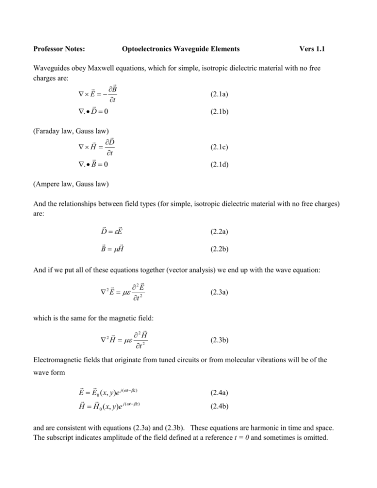
Professor Notes: Optoelectronics Waveguide Elements Vers 1.1 Waveguides obey Maxwell equations, which for simple, isotropic dielectric material with no free charges are: B (2.1a) E t (2.1b) . D 0 (Faraday law, Gauss law) D H t . B 0 (2.1c) (2.1d) (Ampere law, Gauss law) And the relationships between field types (for simple, isotropic dielectric material with no free charges) are: D E (2.2a) B H (2.2b) And if we put all of these equations together (vector analysis) we end up with the wave equation: 2E 2 E 2 (2.3a) t which is the same for the magnetic field: 2H 2 H 2 t (2.3b) Electromagnetic fields that originate from tuned circuits or from molecular vibrations will be of the wave form E E0 ( x, y)e j (t z ) H H 0 ( x, y)e j (t z ) (2.4a) (2.4b) and are consistent with equations (2.3a) and (2.3b). These equations are harmonic in time and space. The subscript indicates amplitude of the field defined at a reference t = 0 and sometimes is omitted. The use of rectangular coordinates (x,y,z) as our basis lets us choose the z-direction as the direction of propagation. The result (2.4a) and (2.4b) then shows that for unconfined electromagnetic waves the oscillating field E= E(x,y) and H = H(x,y) lie in directions that are transverse to the direction of propagation. If the waves are confined and defined by a conduit then the internal reflections will generate components in the direction of propagation. There are two types of conduits that must be considered with optoelectronic systems (1) rectangular and (2) cylindrical. The rectangular geometries are associated with sources, for which a layer is confined in a lateral direction and results in a rectangular cross-section. And then there is the optical fiber, which is almost always cylindrical. The rectangular cross-section has the simplest mathematics. The wave equation in rectangular coordinates is 2E 2E 2E 2E 2 2 (2-5) E x 2 y 2 z 2 t which, using E E0 ( x, y)e j (t z ) , becomes or 2 E0 2 E0 2 E 0 2 E 0 2 2 x y (2-6a) 2 E0 2 E0 2 2 E 0 0 2 2 x y (2-6b) 2 E0 2 E0 2 q E 0 0 x 2 y 2 (2-6c) or (simpler) And similarly for H0. There is still plenty of mathematical overhead since the vector quantity E0 will have components Ex, Ey and Ez all of which have dependence on (x,y). When these are subject to the Maxwell equations (2-1a) and (2-1c) (Faraday law and Ampere law) we end up with six equations. They will resolve into recognizable relationships between Ex, Ey, Ez and Hx , Hy , Hz as follows Ex 1 q2 E H z j z j x y (2-7a) Ey 1 q2 E H z j z j y x (2-7b) Hx 1 q2 E H z j z j y x (2-7c) Hx 1 q2 E H z j z j x y (2-7d) These equations still make no claims to a conduit unless we impose one, for which the solutions would then have boundary conditions. If there are no boundary conditions one of the options would be a freespace wave. And if that is the case, Ez and Hz = 0 and therefore it is necessary that q2 = 0 . And then 2 2 0 (2-8a) And thus for free space, the propagation coefficient 1 c 2f 2 (2-8b) which is usually given the nomenclature k = (free space) wave number, i.e. k 2 (2-8c) If a (rectangular) geometry is imposed as a conduit for the waves, as represented by figure 2.2, then the reflections from the boundaries will insist that Ez and Hz, one or both, are non-zero, and solutions must be of harmonic form (sinand cos), and for which q 2 0 Figure 2-1. Rectangular cross-section of a lightwave conduit (waveguide), dimensions a x b (from http://www.scribd.com/doc/30920866/Wave-Guides) If q 2 0 then equations (2-7a) thru(2-7d) identifies transverse (x,y) components of E and H in terms of the components in the longitudinal (z) direction. As guided waves within a conduit (waveguide) of rectangular cross-section these equations identify relationships between the transverse fields (Ex, Ey, Hx, Hy) and the longitudinal fields (Ez,Hz) of the following types: Transverse Electric (TE) modes: Ez 0 , H z 0 Transverse magnetic (TM) modes: Ez 0 , H z 0 Hybrid modes (EH, HE): Ez 0 , H z 0 As an example, for Ez = 0 (TE modes), and harmonic (sinand cos) solutions of the wave equation (26c), then E and H field components that satisfy the conduit boundary conditions of figure 2-1 are: Ez = 0 Hz = H0 cos(mx/a) cos(ny/b) = H0 cos(kxx) cos(kyy) (2-8a) (2-8b) With transverse components Hx = H0 sin(kxx) cos(kyy) Hy = H0 cos(kxx) sin(kyy) Ex = -E0 cos(kxx) sin(kyy) Ey = E0 sin(kxx) cos(kyy) (2-9a) (2-9b) (2-9c) (2-9d) Obviously we have skipped some fun mathematical overhead and accepted that of others who like such things. But the key context of the results is that there are two wave numbers, one for each geometrical dimension: m = mode number for x-direction = number of ½ within boundaries x = [0, a] n = mode number for y-direction = number of ½ within boundaries y = [0, b] and the specification for TE modes will be of the form TEmn. Typical end-view representations of some of these modes is shown by figure 2.2 Figure 2-2: TE modes, rectangular waveguide (copy from the site http://www.doe.carleton.ca/Courses/ELEC4503/Lectures_2010/Lectures_part3.pdf) These mode numbers also define wave numbers kx and ky for which q 2 k x2 k y2 (2-10a) But p also relates to propagation of waves according to q 2 2 2 k 2 2 (2-10b) (where k = wavenumber for free-space propagation.) So that the propagation coefficient in the waveguide is k 1 k c2 k 2 k 1 C k 2 k x2 k y2 2 (2-10c) If the imposed wavelength is equal to the c specified by (2.10c) then propagation goes to zero (and propagation is cut–off). Propagation therefore requires hat < c , and we can specify this as a cutoff condition, with c being specified by the conduit geometry according to 2 m n C a b 2 2 (2-11) If this condition is extended to three dimensions (i.e. a boundary condition imposed on the z-direction) then equation (2-11) becomes 2 2 m n p C a b c 2 2 (2-12) This is the type of condition associated with semiconductor sources which (as we will see later) have a rectilinear geometry. Equation (2-12) is also the resonance condition for a cavity resonator. Sources should therefore be expected have resonant conditions and TE, TH and hybrid (EH and HE) modes On the other hand the geometry of the optical fiber will be cylindrical and use coordinates (r,z) So for propagation in the z-direction the transverse fields will be of the form E E0 (r, )e j (t z ) H H 0 (r, )e j (t z ) (2.14a) (2.14b) If we identify E in terms of its components Er, E, and Ez and H in terms of its components Hr, H, and Hz , Maxwell equations (2.1a) and (2.1c) in cylindrical coordinates give 1 E z jrE jH r r E z jH r E 1 rE r jH z r r jEr (2-15a) (2-15b) (2-15c) and 1 H z jrH jE r r H z jE r H r 1 rH jE z r r jH r (2-15d) (2-15e) (2-15f) More fun with math will resolve equations (2.15a thru 2.15f) in terms of Ez and Hz as follows: Er j q2 E z H z r r (2-16a) E j q2 H z E z r r (2-16b) Hr j q2 H z E z r r (2-16c) H j q2 E H z z r r (2-16d) where q 2 2 2 since k 2 2 k2 2 (2-17) (free space). The wave equation parameter q2 is the same as for rectilinear coordinates. Therefore much of the same interpretation can be made, except the wave numbers will be associated with (r,) instead of (x,y). If equations (2-16c) and (2-16d) are substituted into equation (2-15f) then 2 E z 1 E z 1 2 Ez q 2 Ez 0 2 2 2 r r r r (2-18) The procedure for solving an equation of this form is to use the separation of variables method for which Ez AF1 (r ) F2 ( ) . The symmetry of the cylindrical geometry suggests that F2() should be of the (sin, cos) form F2()=ej The cylindrical wave equation then gives a differential equation in F1 of the form 2 F1 1 F1 2 2 q 2 F1 0 r 2 r r r (2-19) Equation (2-19) is of the form of Bessel’s equation which is 2 y 1 y 2 1 y 0 x 2 x x x 2 (2-20) Equation (2-20) is the same as equation (2-19) with the substitution x = qr. Solutions are either called Bessel functions or cylindrical functions and are of the designation of either J(x) or K(x), where is an index number associated with the order of the Bessel function. It is not unlike the index number m of the sin(mx) cos(mx) functions associated with the rectilinear geometries. J(x) not a closed function but one generated by an infinite series. Both kinds of Bessel functions are shown by Figure 2-5, plots taken from http://en.wikipedia.org/wiki/Bessel_function (Figure 2-4. Extract from the textbook) Both kinds of Bessel functions are shown by figure 2-5, plots taken from http://en.wikipedia.org/wiki/Bessel_function Inside the core the wave solutions must be finite for r 0 and so the solutions must be of the form of Bessel functions of the first kind J(x). For these functions q 2 k 2 2 must be > 0, and therefore < ( k = k1) is required, where k1 2 1 2 n1 For wave equations outside the core the wave solutions must be finite for r infinity and the solutions must be of the form of Bessel functions of the second kind K(x). This type of Bessel function requires that q2 < 0 and therefore 2 2 n2 > ( k = k2) is required, where k2 2 So wave propagation is bounded by the core and the cladding as identified by the propagation condition (2-21) k2 < < k1 This condition and a lot of fun mathematics leads to cutoff conditions that relate to both kinds of Bessel functions and their derivatives and are defined in terms of the roots (= zeros) of this condition, for which there will be a finite number = m, according to the bounds of the geometry. Otherwise we find that there will be cylindrical modes of the type TEm, TMm, EHm and HEm. Emphasis should be made on the indices, where the first index corresponds to the azmuthal coordinate as well as the Bessel order, and the second condition corresponds to the root of the boundary condition. The four lowest order modes are shown by the textbook figure 2.22. (Figure 2-6. Extract from the textbook) For the dielectric fiber, all modes are hybrid modes except those for which = 0. So there will not be any modes of the form TE11, etc as occur for the rectangular geometries. A summary of these conditions is represented by the (textbook) Table 2-3 Inside the core q 2 k12 2 u 2 Inside the cladding q 2 k 22 2 w 2 . At the boundary, for which r = a the cylindrical functions J(ua) and (wa) must match each other. Each of these functions will realize a set of modes associated with x = ua and x = wa, respectively The number of modes associated with the boundary condition is unified by a single parameter = V called the ‘normalized frequency’ and is the sum V u w a 2 2 2 2a 2 2a 2 2 n1 n2 NA 2 2 2 2a V NA so that (2-22) Parameter V is a dimensionless number that determines how many modes a fiber can support. The relationship between propagation condition 2-21 and the n can be represented graphically by taking the mathematical boundary conditions for the functions and iterating them, for which the result is shown by (extracted) book figure 2.23. The number of modes that can exist in a cylindrical waveguide is also identified by means of a quantity called the normalized propagation constant = b, defined as b 1 au V 2 2 w2 k 2 n12 n22 2 k 22 k 2 n12 n 22 / k 2 n22 n 2 1 n 22 b so that / k 2 n22 n 2 1 n 22 (2-23) Figure 2.23. of textbook, using the Bessel function boundary conditions to define /k vs V. The figure shows that the HE11 mode has no cutoff because its cutoff condition is J1(x) = 0 which is a condition met at r = 0. The figure also shows that for 2a < 2.405 (2-24) V NA corresponding to J0(x) = 0 , TE0m and TM0m and other HE modes are cut off. So equation 2-23 is the condition for a single-mode fiber. The number of modes per solid angle for electromagnetic radiation of wavelength is given by Modes/Solid angle M/ = 2 x (Area/2) (2-25) where the area is the cross-section of the waveguide. Since the solid angle associated with a numerical aperture is approximately sin 2 NA 2 Then M 2 Area 2 2 a 2 V2 2 NA 2 2 (2-26) Equation (2-26) identifies how many modes the fiber will accommodate. From figure 2-23 it is evident that some waveguide modes are alike in their behavior with respect to the normalized frequency V. Since the refractive index of the cladding is very close to that of the core the distinction between these modes becomes blurred and so they are nearly degenerate (realize more than one solution to the underlying mathematics). A synopsis of the groupings (and degeneracies) are given by (textbook) table 2.4 These groupings suggest that a different set of modes need to be defined that are superpositions of these mode groupings. They are given the identification as linearly-polarized modes because the superposed E-fields are linear and exist in modes orthogonal to one another. This characteristic is consistent with the definition of linear polarization. The azmuthal index is then replaced by an index j that follows the rule noted by the grouping, as follows j = 1 for TE and TM modes j = +1 for EH modes j = -1 for HE modes (2-27) The factor 2 that is evident for each of the LPjm modes in table 2-4 is a consequence of the fact that each and every one of these modes have an orthogonal form of the same field cross-section, except orthogonal. This is represented by figures 2-20 and 2-21 for the LP11 mode, which has a 4-fold degeneracy. Consistent with this definition is the behavior of the LP modes with respect to the normalized propagation factor as given by (textbook) figure 2-24 This figure exhibits much the same behavior as figure 2-23. Figure 2-23 displays the results for stiff geometric boundary conditions as specified by the cylindrical differential equations. Figure 2-24 displays the results for soft geometric boundary conditions associated with two refractive indices that are close in value. The single-mode fiber is of special interest. Its two independent degenerate modes are of the orthogonal forms shown by (textbook) figure 2-29 Both polarizations states can be transmitted without interfering with each other. If there is any crosssection flattening, whether intentional or induced, then the degeneracy is lifted and the modes will propagate with different phase velocities. And they will interfere with one another. The difference between the effective refractive indices, nx, and ny for these (orthogonal) modes is called the fiber birefringence, and is given by B f nx n y (2-28) This causes a delay in phase between one mode and the other as they propagate down the fiber and will therefore manifest its phase difference in terms of an interference fiber beat length LP 2 where 2 Bf (2-29) Typical Bf are 10-3 for a high-birefringence fiber to 10-8 for a low-birefringence fiber. http://www.optics.arizona.edu/kost/OPTI%20515%20Web%20Site/Lecture%20Notes/Lecture%2016%2 0Fiber%20Mode%20Profiles%20&%20LP%20Modes.pdf http://cc.ee.ntu.edu.tw/~jfkiang/electromagnetic%20wave/demonstrations/demo_35/im2005_demo_35.h tm
