theoretical ref
advertisement

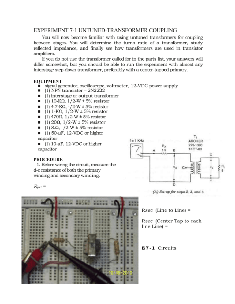
EXPERIMENT 7-1 UNTUNED-TRANSFORMER COUPLING You will now become familiar with using untuned transformers for coupling between stages. You will determine the turns ratio of a transformer, study reflected impedance, and finally see how transformers are used in transistor amplifiers. If you do not use the transformer called for in the parts list, your answers will differ somewhat, but you should be able to run the experiment with almost any interstage step-down transformer, preferably with a center-tapped primary. EQUIPMENT signal generator, oscilloscope, voltmeter, 12-VDC power supply (1) NPN transistor – 2N2222 (1) interstage or output transformer (1) 10-KΩ, 1/2-W ± 5% resistor (1) 4.7-KΩ, 1/2-W ± 5% resistor (1) 1-KΩ, 1/2-W ± 5% resistor (1) 470Ω, 1/2-W ± 5% resistor (1) 20Ω, 1/2-W ± 5% resistor (1) 8.Ω, 1/2-W ± 5% resistor (1) 50-µF, 12-VDC or higher capacitor (1) 10-µF, 12-VDC or higher capacitor PROCEDURE 1. Before wiring the circuit, measure the d-c resistance of both the primary winding and secondary winding. Rpri = Rsec (Line to Line) = Rsec (Center Tap to each line Line) = E 7 - 1 Circuits E 7 - 1 Circuits for experiment 7-1. (continued) 2. Next connect the transformer primary to the signal generator through a 1KΩ resistor, as shown in Fig. E7-1A. Set the generator frequency at 1 KHz, and adjust the amplitude so that the voltage across points A—D measures 4 Vp-p. Measure the primary voltage from point B to D. vBD = Now measure the secondary voltage from point X to Y vxy = Calculate the turns ratio by taking the ratio of the primary voltage to the secondary voltage. n = vp/vs = Since the current flowing in the primary also flows through RA, you can determine the impedance reflected into the primary of T1 by comparing the voltage drop across RA to that across the primary. In other words 3. 180 Electronic Troubleshooting where vab is the voltage across RA and vbd is the voltage across the primary. Substitute for the known values, and solve for 4. r ref Now compare this experimental value Of r ref to the theoretical value. Use your experimental value for n from step 2 above and solve for the reflected impedance. r ref (theoretical) = Next, reconnect your circuit as shown in Fig. E7-1B. Readjust the generator amplitude until you read 4 Vp-p across points A to D again. Measure the voltage from C to D. 5. vCD = Measure the secondary voltage again. vxy. = Calculate the turns ratio now. n= vpri/vsec = Determine the reflected impedance as before. Calculate the theoretical value of reflected impedance. Connect the right end of RA to point B again, as in Fig. E7-1A. Now disconnect the 8Ω load from the secondary. Leave the secondary open circuited. Adjust the generator amplitude to get 4 Vp-p from point A to point D. Now measure the voltage across the transformer primary. 6. vBD = 7. Finally, short out the secondary from point X to point Y with a clip lead. Readjust the generator voltage to 4 Vp-p again. Now measure the voltage across the primary. vBD = Build the circuit of Fig. E7-1 C. Now we will see how the transformer is used in an amplifier. Measure d-c voltages (if your values very significantly from the given – troubleshoot the circuit): 8. VE = 3.05V, __________ VC = 11.5V, _________ 9. Connect an oscilloscope between collector and ground, and adjust vin until vc reads 4 Vp-p. If vc cannot be adjusted down to 4 Vp-p add a 20 dB pad circuit in front of the input Cap. Measure: vin (after pad) = 25mV, _______ What is the voltage gain of the circuit? Av = vc /vin = Also measure the output signal across RL. vo = Now change the connections to the transformer so that the collector sees only half the primary. That is, connect the collector to the center tap of the primary, but leave the power supply connected to one end as before. Leave the other end of the primary disconnected. Again measure: VC = VE = 10. 11. Measure the a-c signal at the collector again. vc = Now calculate the voltage gain. Av = vc /vin = Measure vo across RL again. vo = Leave the transformer primary connected as in step 10, but change RL to 22 Ω. Do not change vin. Measure: 12. vc = vo = How do these values compare to those of Step 11? QUIZ 1. Based on your calculated value of turns ratio n in step 2, what voltage would you expect to measure across the load if vp = 6 Vpp? Vs = 2. If the generator in step 2 were adjusted to 6 Vpp and if RL = 20 Ω, what voltage should appear across points B and D? vbd = In step 5, connecting the generator to the primary center tap— (a) doubled, (b) halved—the turns ratio and caused the reflected impedance to be—(c) half, (d)one quarter, (e)twice, (f)four times— as great as in step 1. 3. Step 6 showed that an open secondary reflects a very—(a) high, (b) low impedance back into the primary. 4. 5. In step 7, short circuiting the secondary reflects a very—(a) high, (b) low impedance into the primary. The d-c measurements in Step 8 showed that (a)the transistor was cut off. (b) the transistor was saturated. (c) there was very little d-c across the transformer primary. 6. 182 Electronic Troubleshooting The fact that an a-c voltage could be measured at the collector in step 9 showed that (a) the transistor sees a high a-c resistance, even though the d-c resistance is low. (b) the a-c signal is developed across the low d-c resistance of the transformer. 7. 8. When viewing the signal at the collector, we see that the peak voltage appearing across the transistor---(a)does, (b)does not— exceed the power supply voltage In step 11, the voltage gain—(a) went up, (b) went down, (c) remained the same—compared to step 9, because the reflected impedance was (d)higher. (e) lower. (f)the same. 9. Step 12 showed that the voltage gain—(a) increases, (b) decreases, (c) remains the same—if the secondary load is increased. 10.


