SupplementalMaterial_final
advertisement
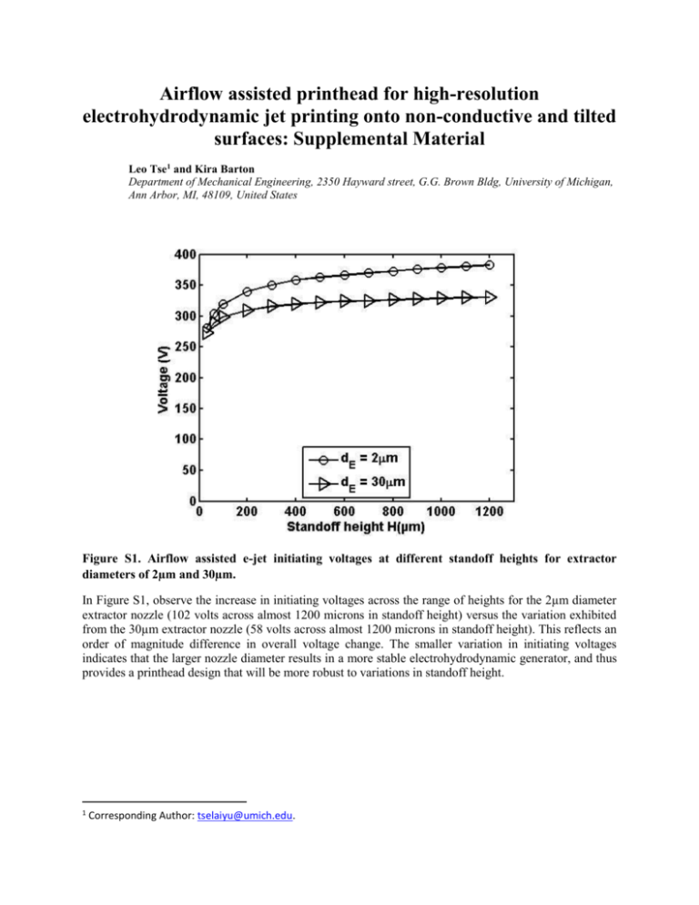
Airflow assisted printhead for high-resolution electrohydrodynamic jet printing onto non-conductive and tilted surfaces: Supplemental Material Leo Tse1 and Kira Barton Department of Mechanical Engineering, 2350 Hayward street, G.G. Brown Bldg, University of Michigan, Ann Arbor, MI, 48109, United States Figure S1. Airflow assisted e-jet initiating voltages at different standoff heights for extractor diameters of 2µm and 30µm. In Figure S1, observe the increase in initiating voltages across the range of heights for the 2µm diameter extractor nozzle (102 volts across almost 1200 microns in standoff height) versus the variation exhibited from the 30µm extractor nozzle (58 volts across almost 1200 microns in standoff height). This reflects an order of magnitude difference in overall voltage change. The smaller variation in initiating voltages indicates that the larger nozzle diameter results in a more stable electrohydrodynamic generator, and thus provides a printhead design that will be more robust to variations in standoff height. 1 Corresponding Author: tselaiyu@umich.edu. Figure S2. Print quality as a function of air jetting nozzle diameter d A , pressure PA , and distance between the printing and extractor nozzles S . Note that for air nozzle diameters of dA = 2 or 5µm the airflow is not strong enough to overcome the electrohydrodynamics and redirect the ejected droplets onto the substrate. For a nozzle diameter of dA = 30µm, the range of airflow that can be used to redirect the ink droplets only spans 3 psi; increasing the sensitivity of the process to changes in airflow and making process optimization extremely challenging. For nozzle diameters of dA = 10µm, the range of airflow that can be used to redirect the ink droplets spans 10psi, which allows the user to optimize the printing conditions for improved printing performance. Evaluating the impact of the distance between the printing and extractor nozzles for the optimal air nozzle, we observed the best printing conditions for S=10dN. For S<10dN , the ink droplets were strongly attracted to the extractor nozzle, requiring larger airflow pressures and increased sensitivity to changes in the air pressure. For S>10dN, although the pressures ranges remained fairly consistent, the increased distance between the printing and extractor nozzles increased the role of the substrate in the electrohydrodynamics. Thus, the change in voltage across the range of heights increased, more closely following the behavior of the conventional e-jet setup. Figure S3. Spiral patterns printed using a DC voltage signal applied to an airflow assisted e-jet printhead that is printing onto tilted surfaces. Three spiral patterns printed with airflow assisted e-jet printhead using DC voltage signal are provided in Figure S3. The spirals are printed onto three surfaces tilted at different angles (25°, 45° and 60°), while maintaining the same voltage settings and only allowing the printhead to move in the XY plane. Due to the differences caused by the tilted angles of the substrates, the three patterns result in printed patterns with different variations in standoff height throughout the printing process. The consistency in the printing quality across these variations in standoff height (116 – 536µm) demonstrate the ability of the airflow assisted e-jet printhead to print patterns across large changes in standoff height, while maintaining the resolution and quality throughout the pattern. Note that although the printhead is able to print droplets and overlap the droplets to provide a continuous line, discontinuities can be observed in the patterns. These irregularities are a result of the beading phenomenon often observed in materials with high cohesive forces. For these materials, the cohesive force within the ink material is stronger than the adhesive force between the ink and the substrate; thus resulting in the beading pattern observed throughout the pattern that leads to discontinuity. Future work will address this issue. α β 1mm Figure S4. Electrostatic field in airflow assisted E-jet printhead. This rainbow plot is generated with COMSOL Multiphysics 4.4. It presents the potential levels of the electrostatic field within an airflow assisted e-jet printhead, with red representing the highest potential and blue representing grounded level potential. The grey lines are indicating the outer profiles of the nozzles. Notice the electrostatic field creates a strong horizontal force upon the ink droplets towards the extractor nozzle (the blue grounded area). Using this model, larger angles of α and β were shown to result in stronger attractive forces in the horizontal direction. Experimentally, these forces led to more droplets being directed towards the extractor nozzle and increased scattering on the printed pattern. The parameters used in to generate the COMSOL model are provided in table S1. Table S1. Simulation parameters used in the electrostatic field COMSOL model. Parameter dN dE V α β h S Ink relative permittivity Nozzle material (glass) relative permittivity Substrate material (glass) relative permittivity Value 2µm 30 µm 315V 30° 30° 400µm 20µm 80.1 4.7 4.7
