Period 8 THz data v02
Period 8. THz
(YMS)
THz signals.
Initial observations (large area detector near diamond window).
Initially, the THz large area detector was installed next to the output diamond window, next to the compression chicane. The calibration factor was ~ 1mV per ~1
J of total THz pulse energy (have to check this though).
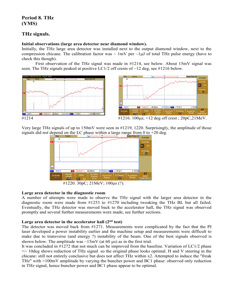
First observation of the THz signal was made in #1214, see below. About 15mV signal was seen. The THz signals peaked at positive LC1/2 off crests of ~12 deg, see #1216 below.
#1216. 100
s; +12 deg off crest ; 20pC,21MeV. #1214
Very large THz signals of up to 150mV were seen in #1219, 1220. Surprisingly, the amplitude of those signals did not depend on the LC phase within a large range from 0 to +20 deg.
30pC; 21MeV; 100
s (?).
Large area detector in the diagnostic room
A number of attempts were made to observe the THz signal with the larger area detector in the diagnostic room were made from #1253 to #1270 including tweaking the THz BL but all failed.
Eventually, the THz detector was moved back to the accelerator hall, the THz signal was observed promptly and several further measurements were made, see further sections.
Large area detector in the accelerator hall (2 nd test)
The detector was moved back from #1271. Measurements were complicated by the fact that the PI laser developed a power instability earlier and the machine setup and measurements were difficult to make due to transverse (and energy ?) instability of the beam. One of the best signals observed is shown below. The amplitude was ~15mV (at 60
s) as in the first trial.
It was concluded in #1272 that not much can be improved from the baseline. Variation of LC1/2 phase
+/- 10deg shows reduction of THz signal so the original phase looks optimal. H and V steering in the chicane: still not entirely conclusive but does not affect THz within x2. Attempted to induce the "freak
THz" with >100mV amplitude by varying the buncher power and BC1 phase: observed only reduction in THz signal, hence buncher power and BC1 phase appear to be optimal.
#1272. 60
s; 20pC; 20.8MeV
Effect of beam steering on THz generation.
Initial observations.
This has been investigated with the large area detector being still next to the diamond window (#1220).
The energy recovery was unstable even after reducing the bunch charge to ~15pC. And this affected also the THz signal stability. This made the steering experiment not exactly accurate but we may nevertheless conclude that the THz signal does not depend (within a factor of x2) on beam steering through the compression chicane. Observations and trajectory modelling are as follows:
The initial setting of the chicane was: DIP-01/02/03/04 = 52.40 / 52.60 / 52.65 / 52.40 (see trajectory below). Bunch charge = 15pC. THz signal was ~ 20mV amplitude.
All dipoles increased by 1.2A : energy recovery started to get worse but no change in THz signal.
DIP-02 = +0.5A and DIP-03 = -0.5A : energy recovery nearly lost; beam moved by ~5mm on ST2-
BPM-04; THz did not change.
DIP-03 = +0.8A , DIP-04 = + 0.55A : here DIP-04 was adjusted such that to keep the beam on ST3-1 in the same position; there was some 50% change in THz but eventually it settled to original level. The trajectory “A” , - see below.
DIP-03 = - 4.0A , DIP-04 = -4.05 A : Trajectory “B”, here we moved the beam between DIP-03 and
DIP-04 in the opposite direction compared to Trajectory “A”; DIP-04 was adjusted such that to restore energy recovery. No change in THz.
Trajectory “C” : decreased DIP-02 to move the beam to the outer wall at DIP-03 position.
Trajectory “D” : the THz at this settings seemed to reduce by a factor of x2 but when the initial settings were restored the THz signal was lower as well ; hence the other reason, not steering, could change the level of THz.
Initial setting.
DIP = 52.40 / 52.60 / 52.65 / 52.40
Trajectory “A”
DIP = 52.40 / 52.60 / 53.45 / 52.95
Trajectory “B”
DIP = 52.40 / 52.60 / 47.85 / 48.35
Trajectory “C”
DIP = 52.40 / 51.00 / 45.95 / 54.10
Trajectory “D”
DIP = 53.20 / 53.40 / 52.75 / 52.75
We conclude therefore that the steering is unlikely to affect the THz level at the beginning of the THz beamline. Electron beam steering may still affect the THz beam transport through the THz beamline but this is a subject for a different experiment.
Wide range measurements.
At Q~20pC, the THz signal with the detector positioned next to the diamond window, is not affected whether the energy recovery is sustained or not. This was demonstrated in #1272. This allows to vary the e-beam trajectories in the compression chicane in a very wide range.
In #1272, the beam was steered with the chicane DIP-03 in a very large range of +/- 5A (that is +/-
10% of nominal !). No appreciable variation of the THz signal was observed within this large range.
This experiment demonstrated comprehensively that the THz generation does not depend on the beam steering within the compression chicane.
Also, at > (+5A) on DIP-03, strange observation was made: the THz signal (the same pulse shape, duration ) becomes POSITIVE (normally it's negative) – see below.
DIP-03 = 47A DIP-03 = 57A DIP-03 = 58A
One possible explanation could be that the THZ detector electronics becomes affected by the x-rays produced by the beam lost between the chicane dipoles DIP-03 and DIP-04.
THz v beam characteristics
Observations from #1272.
When the beam is "spoiled" by inserting ST2-3 (in the chicane) - THz signal is reduced by at least a factor of 2.
Changing ST2-Q-03/04 certainly affects the THz signal . This implies that the transverse profile of the beam is of importance for the THz generation.
------------------------------------------------------------


