Carl Stahoviak P15462 Design Analysis Studies Static & Dynamic
advertisement
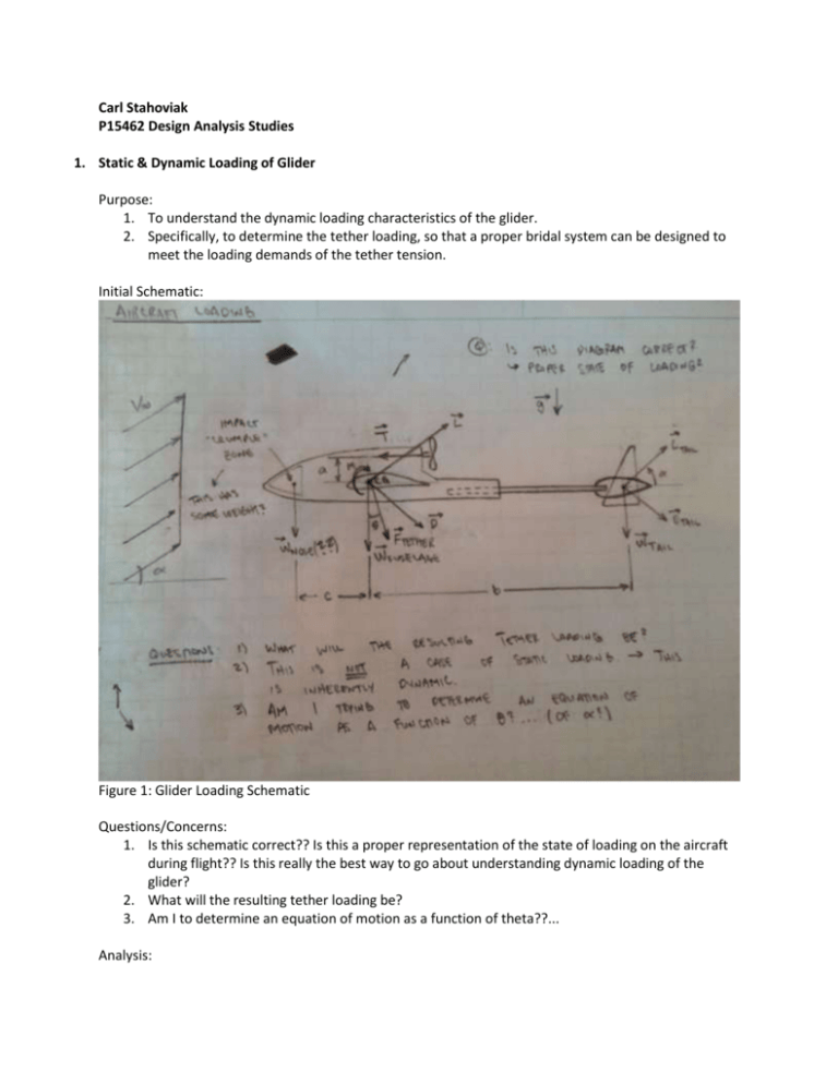
Carl Stahoviak P15462 Design Analysis Studies 1. Static & Dynamic Loading of Glider Purpose: 1. To understand the dynamic loading characteristics of the glider. 2. Specifically, to determine the tether loading, so that a proper bridal system can be designed to meet the loading demands of the tether tension. Initial Schematic: Figure 1: Glider Loading Schematic Questions/Concerns: 1. Is this schematic correct?? Is this a proper representation of the state of loading on the aircraft during flight?? Is this really the best way to go about understanding dynamic loading of the glider? 2. What will the resulting tether loading be? 3. Am I to determine an equation of motion as a function of theta??... Analysis: Recommended Design Choices: 1. We need to come up with a consistent set of drawings from which all of us can work. 2. Boom Loading Purpose: 1. To estimate the stress that the longitudinal boom will be subject to during flight at the point of connection to the foam body of the glider. 2. To use this estimation to select a diameter of Carbon Fiber tubing that will be able to handle the estimated stress multiplied by a factor of safety. Initial Schematic: Figure 2: Boom Loading Schematic Questions: 1. Should we use a solid or hollow boom? For the purposes of weight savings, it would seem that hollow would be the smart choice… Analysis: Cantilever Beam – Concentrated Load at Free End For a given boom cross section, maximum stress located at the outer fiber is given by: 𝜎𝑚𝑎𝑥 = 𝑀𝑐 𝑀𝑅 𝑀𝐷 = = 𝐼 𝐼 2𝐼 From Figure 2, we can see that: 𝑀 = [𝐿 − 𝑊𝑡𝑎𝑖𝑙 ]𝑎 𝑀 = [𝐿 − (𝑊ℎ𝑜𝑟𝑖𝑧 𝑡𝑎𝑖𝑙 + 2𝑊𝑟𝑢𝑑𝑑𝑒𝑟 + 𝑊𝑠𝑝𝑎𝑟 )]𝑎 1 𝑀 = |𝐿𝑎 − [𝑐𝑡 𝑙𝑡 ( 𝑡𝑚𝑎𝑥 ) 𝜌𝑓𝑜𝑎𝑚 + 2𝑟𝑙 𝑟ℎ 𝑟𝑡 𝜌𝑓𝑜𝑎𝑚 + 𝐴𝑠𝑝𝑎𝑟 𝑙𝑠𝑝𝑎𝑟 𝜌𝑐𝑓 ] 𝑔𝑎| 2 𝐴𝑠𝑝𝑎𝑟 = 𝜋 2 (𝐷 − 𝐷𝑖2 ) 4 𝑜 For either a solid or hollow circular boom cross section, the moment of inertia about the bending axis is: 𝜋 𝐼 = 64 𝐷02 𝜋 𝐼 = 64 (𝐷02 − 𝐷𝑖2 ) (Solid) (Hollow) Now, we’ll rearrange the equation for max stress in the cross section, to solve for D o 𝜎𝑚𝑎𝑥 = 𝑀𝐷 𝑀∗ 𝐷 = , 2𝐼 2𝐼 𝐷𝑜 = 𝑀∗ = 𝑀 ∙ 𝐹𝑜𝑆, 𝐹𝑜𝑆 = 4 2𝜎𝑚𝑎𝑥 𝐼 𝑀∗ For Carbon Fiber, σmax = 300 ksi. For our purposes, we will take σmax = 30 ksi so that we are working with bending stresses that are well below the maximum bending stress that carbon fiber can take. Now, to solve for the minimum outer diameter, D0, for a solid carbon fiber beam subject to a maximum bending stress of σmax = 3 ksi. 𝐷𝑜 = −1 2𝜎𝑚𝑎𝑥 𝜋 2 1 ∙ 𝐷0 ∙ |𝐿𝑎 − [𝑐𝑡 𝑙𝑡 ( 𝑡𝑚𝑎𝑥 ) 𝜌𝑓𝑜𝑎𝑚 + 2𝑟𝑙 𝑟ℎ 𝑟𝑡 𝜌𝑓𝑜𝑎𝑚 + 𝐴𝑠𝑝𝑎𝑟 𝑙𝑠𝑝𝑎𝑟 𝜌𝑐𝑓 ] 𝑔𝑎| 𝐹𝑜𝑆 64 2 The maximum lift generated by the horizontal tail will occur when the elevator is at its maximum deflection, as pictured below. Lift can be calculated as follows: 1 2 𝐿 = 𝜌𝑣∞ 𝑆𝐶𝐿 , 2 𝐶𝐿 ≅ 1.0 Finally, before solving the final equation, we will make the Lift and Weight terms additive rather than subtractive, to yield the maximum possible bending moment. This gives a minimum outer diameter, Do −1 2𝜎𝑚𝑎𝑥 𝜋 2 1 𝐷𝑜 = ∙ 𝐷 ∙ |𝐿𝑎 + [𝑐𝑡 𝑙𝑡 ( 𝑡𝑚𝑎𝑥 ) 𝜌𝑓𝑜𝑎𝑚 + 2𝑟𝑙 𝑟ℎ 𝑟𝑡 𝜌𝑓𝑜𝑎𝑚 + 𝐴𝑠𝑝𝑎𝑟 𝑙𝑠𝑝𝑎𝑟 𝜌𝑐𝑓 ] 𝑔𝑎| 𝐹𝑜𝑆 64 0 2 𝑫𝒐 = 𝟎. 𝟔𝟏𝟕𝟖 𝒊𝒏 Conclusion: 1. For our carbon fiber boom, an outer diameter, Do = 0.6178 in, the maximum stress in the cross section will be 7.5 ksi, which is well below the maximum bending stress, σmax = 300 ksi, that carbon fiber tubes are able to handle 2. We will choose a carbon fiber boom diameter of 0.50 inches for our design. 3. Horizontal Spar Loading Purpose: 1. To estimate the stress that the horizontal spar(s) will be subject to during flight at the point of connection to the foam body of the glider. 2. To use this estimation to select a diameter of Carbon Fiber tubing that will be able to handle the estimated stress multiplied by a factor of safety. 3. To determine whether 1 or 2 spar(s) would be best suited to handling the wing moment as well as provide pitch stability to the glider. Initial Schematic: Figure 3: Spar Loading Schematic Figure 4: Spar Loading Schematic Questions/Concerns: 1. What factors affect the moment, M, that that spars are subject to? a. Glider speed b. Wind dimensions c. Wing taper? d. Number/dimensions of internal spar? e. Material Choice of wing/spar 4. Foam Compression Testing Purpose: 1. To perform a compressive test on 6 foam samples in order to determine the equivalent spring stiffness of Expanded Polypropylene (EPP) foam. Initial Schematic: Figure 5: EPP Foam Samples Questions/Concerns: 1. Do we have the proper compressive testing hardware to perform this test? -> YES, we do. This has been confirmed with Prof. Humphrey. 2. Are we going to be able to schedule time on the machine to perform this test? -> YES, this will happen in the next week, prior to November 21st. Analysis: Conclusions: 5. Foam Coating Purpose: 2. To choose a coating for our foam that will be able to adhere to the surface of the foam without melting or deforming the foam during the adhesive process. 3. The coating will serve two main purposes: a. Reduce skin friction drag b. Weatherproof the foam Initial Schematic: Figure 6: Foam Coating Info Analysis: 1. A sample of EPP was successfully coated with MonoKote. Conclusions: 1. MonoKote is readily available, and a well-regarded foam coating material that is suitable for use with EPP 2. MonoKote has been proven to adhere to our EPP foam without damaging or deforming the foam itself. 3. We will use MonoKote to coat our foam.

