Joseph
advertisement
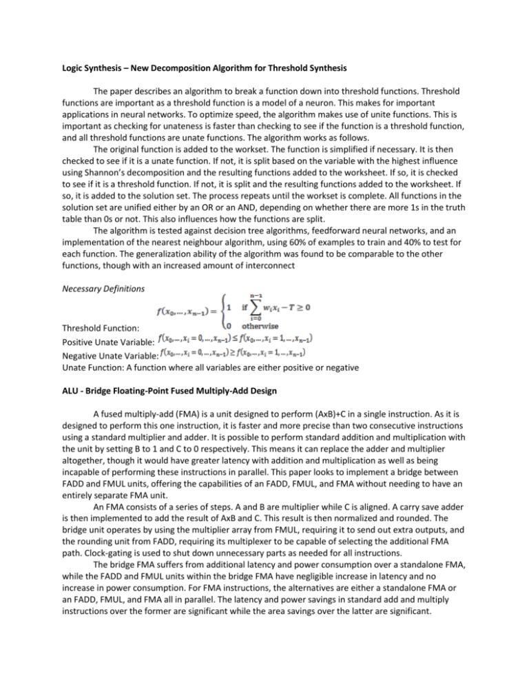
Logic Synthesis – New Decomposition Algorithm for Threshold Synthesis The paper describes an algorithm to break a function down into threshold functions. Threshold functions are important as a threshold function is a model of a neuron. This makes for important applications in neural networks. To optimize speed, the algorithm makes use of unite functions. This is important as checking for unateness is faster than checking to see if the function is a threshold function, and all threshold functions are unate functions. The algorithm works as follows. The original function is added to the workset. The function is simplified if necessary. It is then checked to see if it is a unate function. If not, it is split based on the variable with the highest influence using Shannon’s decomposition and the resulting functions added to the worksheet. If so, it is checked to see if it is a threshold function. If not, it is split and the resulting functions added to the worksheet. If so, it is added to the solution set. The process repeats until the workset is complete. All functions in the solution set are unified either by an OR or an AND, depending on whether there are more 1s in the truth table than 0s or not. This also influences how the functions are split. The algorithm is tested against decision tree algorithms, feedforward neural networks, and an implementation of the nearest neighbour algorithm, using 60% of examples to train and 40% to test for each function. The generalization ability of the algorithm was found to be comparable to the other functions, though with an increased amount of interconnect Necessary Definitions Threshold Function: Positive Unate Variable: Negative Unate Variable: Unate Function: A function where all variables are either positive or negative ALU - Bridge Floating-Point Fused Multiply-Add Design A fused multiply-add (FMA) is a unit designed to perform (AxB)+C in a single instruction. As it is designed to perform this one instruction, it is faster and more precise than two consecutive instructions using a standard multiplier and adder. It is possible to perform standard addition and multiplication with the unit by setting B to 1 and C to 0 respectively. This means it can replace the adder and multiplier altogether, though it would have greater latency with addition and multiplication as well as being incapable of performing these instructions in parallel. This paper looks to implement a bridge between FADD and FMUL units, offering the capabilities of an FADD, FMUL, and FMA without needing to have an entirely separate FMA unit. An FMA consists of a series of steps. A and B are multiplier while C is aligned. A carry save adder is then implemented to add the result of AxB and C. This result is then normalized and rounded. The bridge unit operates by using the multiplier array from FMUL, requiring it to send out extra outputs, and the rounding unit from FADD, requiring its multiplexer to be capable of selecting the additional FMA path. Clock-gating is used to shut down unnecessary parts as needed for all instructions. The bridge FMA suffers from additional latency and power consumption over a standalone FMA, while the FADD and FMUL units within the bridge FMA have negligible increase in latency and no increase in power consumption. For FMA instructions, the alternatives are either a standalone FMA or an FADD, FMUL, and FMA all in parallel. The latency and power savings in standard add and multiply instructions over the former are significant while the area savings over the latter are significant. DFP – A DFP Adder with Decoded Operands and a Decimal Leading-Zero Anticipator Decimal floating-point arithmetic has become important for many commercial and monetary applications, where the inaccuracies in binary floating-point arithmetic begin to add up. Naturally, improving the speed of the base operations is important to ensure high speeds of overall operation. This paper looks to improve the latency of the DFP adder through the use of a new internal format and a Leading-Zero Anticipator (LZA). Leading-zero detection is the act of finding the location of the most significant non-zero bit. A leading-zero anticipator finds the most significant non-zero bit using the operator and operands without actually calculating the result. The leading-zero count (LZC) is the numerical value defining the location of the most significant non-zero bit. The DFP adder uses a new internal format that keeps track of the leading zero count. This removes the need for leading-zero detection through the critical path. The lead zero count is used as an input signal. The leading-zero anticipator works in parallel with the adding operation to find the leadingzero count of the output. In addition, the preliminary LZC is the minimum LZC between the two significands being added. In the event of a carry, the final LZA becomes that value reduced by one. In subtraction, the preliminary LZC is found as in addition. The incoming values then produce a variety of flags, which, through Boolean logic based on predetermined string patterns, determine how the preliminary LZC should be modified. The proposed adder is tested on randomly generated cases and IBM’s corner cases to verify correctness. It is compared against the previous adder design and found to be 14% faster but with 18% more area. The LZA is found to have a maximum delay of 24 F04 inverter delays. Cache – Efficient Use of Multibit Error-Correcting Codes in L2 Cache As CMOS technology shrinks, the number of random defects increases. These defects are traditionally treated with redundant replacement rows, columns, and words. However, as random defects increase, redundancy alone may no longer be sufficient. This paper looks to extend the role of Error-Correcting Codes (ECC) to make up for these defects. ECC are codes that can be used to correct an error in data. They are traditionally used to correct soft transient errors. Multi-bit ECC (M-ECC) can correct multiple errors in data, though they have larger latency. This makes it unusable in L1 cache, though selective use in L2 cache may yet be reasonable. Cache blocks with multiple defects are identified during memory testing. Content-Addressable Memory (CAM) is then used to identify these blocks during runtime. The traditional L2 cache is used for subblocks with one or less defects. A M-ECC cache core is used for subblocks with two defects (referred to as m-blocks). Subblocks with three or more defects are repaired through redundancy. As M-ECC has larger latency and energy consumption, two additional buffers are used to reduce how often it is accessed. The pre-decoding buffer is a cache that keeps copies of recently accessed mblocks. The FLU buffer is a small CAM that keeps addresses of recently accessed blocks that aren’t mblocks. Both use a LRU policy and effectively reduce M-ECC cache access. With ECC devoted to defect tolerance, data integrity becomes an issue due to soft errors. In the case of clean blocks, the data can be restored from memory. A solution is therefore needed for dirty blocks. A dirty replication (DR) cache is used. When a block is made dirty, data is duplicated in the cache. Data leaving the DR cache is written to main memory. Therefore, data backup is always available. The pre-decoding buffer, FLU buffer, and DR cache must all be 64-blocks for consistent results across platforms. IPC performance is nearly the same as a defect-free L2 cache. Power on average is 36% more than a defect-free L2 cache, though this is reasonable as the L2 cache power consumption is 10% of the entire system cache. It uses 2.5% more area than an L2 cache alone.


