docx - Microsoft Research
advertisement
Spherical Parametrization and Remeshing
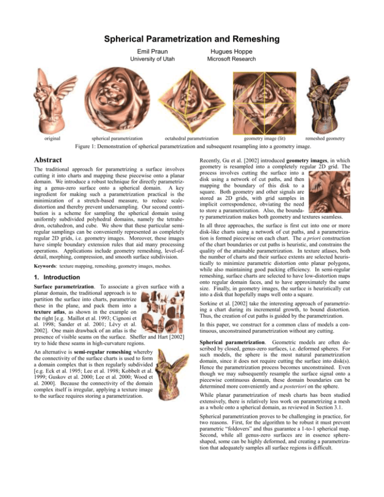
original
Emil Praun
Hugues Hoppe
University of Utah
Microsoft Research
spherical parametrization
octahedral parametrization
geometry image (lit)
remeshed geometry
Figure 1: Demonstration of spherical parametrization and subsequent resampling into a geometry image.
Abstract
The traditional approach for parametrizing a surface involves
cutting it into charts and mapping these piecewise onto a planar
domain. We introduce a robust technique for directly parametrizing a genus-zero surface onto a spherical domain. A key
ingredient for making such a parametrization practical is the
minimization of a stretch-based measure, to reduce scaledistortion and thereby prevent undersampling. Our second contribution is a scheme for sampling the spherical domain using
uniformly subdivided polyhedral domains, namely the tetrahedron, octahedron, and cube. We show that these particular semiregular samplings can be conveniently represented as completely
regular 2D grids, i.e. geometry images. Moreover, these images
have simple boundary extension rules that aid many processing
operations. Applications include geometry remeshing, level-ofdetail, morphing, compression, and smooth surface subdivision.
Keywords: texture mapping, remeshing, geometry images, meshes.
1. Introduction
Surface parametrization. To associate a given surface with a
planar domain, the traditional approach is to
partition the surface into charts, parametrize
these in the plane, and pack them into a
texture atlas, as shown in the example on
the right [e.g. Maillot et al. 1993; Cignoni et
al. 1998; Sander et al. 2001; Lévy et al.
2002]. One main drawback of an atlas is the
presence of visible seams on the surface. Sheffer and Hart [2002]
try to hide these seams in high-curvature regions.
An alternative is semi-regular remeshing whereby
the connectivity of the surface charts is used to form
a domain complex that is then regularly subdivided
[e.g. Eck et al. 1995; Lee et al. 1998; Kobbelt et al.
1999; Guskov et al. 2000; Lee et al. 2000; Wood et
al. 2000]. Because the connectivity of the domain
complex itself is irregular, applying a texture image
to the surface requires storing a parametrization.
Recently, Gu et al. [2002] introduced geometry images, in which
geometry is resampled into a completely regular 2D grid. The
process involves cutting the surface into a
disk using a network of cut paths, and then
mapping the boundary of this disk to a
square. Both geometry and other signals are
stored as 2D grids, with grid samples in
implicit correspondence, obviating the need
to store a parametrization. Also, the boundary parametrization makes both geometry and textures seamless.
In all three approaches, the surface is first cut into one or more
disk-like charts using a network of cut paths, and a parametrization is formed piecewise on each chart. The a priori construction
of the chart boundaries or cut paths is heuristic, and constrains the
quality of the attainable parametrization. In texture atlases, both
the number of charts and their surface extents are selected heuristically to minimize parametric distortion onto planar polygons,
while also maintaining good packing efficiency. In semi-regular
remeshing, surface charts are selected to have low-distortion maps
onto regular domain faces, and to have approximately the same
size. Finally, in geometry images, the surface is heuristically cut
into a disk that hopefully maps well onto a square.
Sorkine et al. [2002] take the interesting approach of parametrizing a chart during its incremental growth, to bound distortion.
Thus, the creation of cut paths is guided by the parametrization.
In this paper, we construct for a common class of models a continuous, unconstrained parametrization without any cutting.
Spherical parametrization. Geometric models are often described by closed, genus-zero surfaces, i.e. deformed spheres. For
such models, the sphere is the most natural parametrization
domain, since it does not require cutting the surface into disk(s).
Hence the parametrization process becomes unconstrained. Even
though we may subsequently resample the surface signal onto a
piecewise continuous domain, these domain boundaries can be
determined more conveniently and a posteriori on the sphere.
While planar parametrization of mesh charts has been studied
extensively, there is relatively less work on parametrizing a mesh
as a whole onto a spherical domain, as reviewed in Section 3.1.
Spherical parametrization proves to be challenging in practice, for
two reasons. First, for the algorithm to be robust it must prevent
parametric “foldovers” and thus guarantee a 1-to-1 spherical map.
Second, while all genus-zero surfaces are in essence sphereshaped, some can be highly deformed, and creating a parametrization that adequately samples all surface regions is difficult.
To address these challenges, our parametrization algorithm borrows techniques from Sander et al. [2001, 2002]. We achieve
robustness using a coarse-to-fine optimization strategy, and
penalize undersampling using a stretch-based parametrization
metric (Section 3). Intuitively, stretch measures how distances in
the domain get scaled onto the surface. Large stretch in any
direction about a surface point implies that the reconstruction of
the surface signal from a domain-uniform sampling will lose highfrequency surface detail.
2. Approach overview
Given a surface mesh 𝑀, our goal is to create a geometry image 𝐼
that approximates it. We first create a spherical parametrization
of the surface (𝑆 → 𝑀). Next, we similarly create a spherical
parametrization (𝑆 → 𝐷) of a domain polyhedron 𝐷, chosen to be
a tetrahedron, an octahedron, or a cube. Finally, we unfold the
domain into the image (𝐷 → 𝐼). All these maps are invertible, and
their composition provides a map 𝐼 → 𝐷 → 𝑆 → 𝑀 (see Figure 2).
Once a spherical parametrization is obtained, a number of applications can operate directly on the sphere domain, including shape
analysis using spherical harmonics [Funkhouser et al. 2003;
Quicken et al. 2000], compression using spherical wavelets
[Schröder and Sweldens 1995], and mesh morphing [Alexa 2002].
For remeshing, we uniformly sample the domain polyhedron at
the vertices of a regular 𝑛-tessellation (𝑛 + 1 vertices on each
domain edge). As explained in Section 4.1, the unfolding (𝐼 ↔ 𝐷)
is not an isometry and we are not concerned with its metric
distortion – it is a convenient scheme for associating the domain
samples 1-to-1 with the 2D grid samples of the image.
Spherical remeshing. Many techniques rely on sampled representations, and unfortunately, the only truly uniform samplings of
the sphere are given by the vertices of the 5 Platonic solids (icosahedron being the most complex with 20 vertices).
To avoid undersampling of the surface mesh, we seek to minimize
the stretch of the map 𝐷 → 𝑀. We do this by minimizing stretch
on the two maps 𝐷 → 𝑆 and 𝑆 → 𝑀. Both maps involve the
computation of a spherical parametrization, as discussed next.
In computer graphics, spherical functions such as environment
and visibility maps are often represented using cube maps [Greene
1986]. While this cube projection is hardware-efficient, it creates
a rather non-uniform spherical sampling (with stretch varying by a
factor of 3). Unlike in environment maps, spherical directions
have no special meaning for surface parametrizations. Thus we
are free to construct maps that distribute samples more uniformly.
As a sampling pattern, we use the vertices of uniformly subdivided regular polyhedra, namely the tetrahedron, octahedron, and
cube. We explore maps with minimal stretch from these domains
to the sphere (Section 4.2).
Geometry images. The semi-regular samples that we construct
over the polyhedral domains can in fact be cut and unfolded such
that they correspond 1-to-1 with a regular 2D grid (Section 4.1).
We use these unfoldings to resample our spherical parametrizations into geometry images (see Figure 1).
The simple 2D grid structure of geometry images is ideally suited
for many processing operations. For instance, they can be rendered by traversing the grids sequentially, without expensive
memory-gather operations (such as vertex index dereferencing or
random-access texture filtering). Geometry images also facilitate
compression and level-of-detail control.
The geometry images introduced by Gu et al. [2002] support
surfaces of arbitrary genus by allowing an arbitrary surface cut.
However, the cut topology must be stored explicitly for lossy
decompression, and it constrains level-of-detail mip-mapping.
In contrast, our construction is specialized to genus-zero surfaces,
and the topology of our polyhedral cuts is fixed and simple. The
cuts give rise to symmetry rules at the image boundaries, which
enable morphing, better level-of-detail control, more effective
compression, and the creation of smooth surfaces.
3. Spherical parametrization
Given a triangle mesh 𝑀, the problem of spherical parametrization is to form a continuous invertible map 𝜙: 𝑆 → 𝑀 from the
unit sphere to the mesh. The map is specified by assigning each
mesh vertex 𝑣 a parametrization 𝜙 −1 (𝑣) ∈ 𝑆. Each mesh edge is
mapped to a great circle arc, and each mesh triangle is mapped to
a spherical triangle bounded by these arcs.
3.1 Previous work
Kent et al. [1992] propose several spherical parametrization
schemes. For general shapes, they simulate a balloon inflation
process, but are not able to guarantee a 1-to-1 map.
Alexa [2002] uses a spring-like relaxation process. The relaxation
solutions may collapse to a point, or experience foldovers, depending on the starting state. He demonstrates several heuristics
that help the solution converge to valid maps.
Grimm [2002] partitions the surface into 6 charts, and maps these
to faces of a cube, and from there to a sphere. Schemes based on
a priori chart partitions constrain the spherical parametrization.
Haker et al. [2000] find conformal approximations of meshes over
the sphere. Conceptually, they remove a single point from the
surface, harmonically map the remaining surface onto an infinite
plane, and finally map that infinite plane onto the sphere using
stereographic projection. Both maps are conformal for smooth
surfaces. Unfortunately, many maps that are bijective and conformal for smooth surfaces do not guarantee an embedding when
applied to piecewise-linear surfaces (meshes), and sometimes
produce triangle flips, as in Eck et al. [1995]. For instance,
stereographic projection can flip thin obtuse triangles. Another
concern with conformal-like maps is scale distortion (Figure 11).
Sheffer et al. [2003] find the angles of a spherical embedding as a
constrained nonlinear system, and show results for simple meshes.
Gotsman et al. [2003] show a nice relationship between spectral
graph theory and spherical parametrization, and embed simple
meshes on the sphere by solving a quadratic system.
Quicken et al. [2000] parametrize the surface of a voxel volume
onto a sphere. Their nonlinear objective functional exploits the
uniform quadrilateral structure of the voxel surface; it seeks to
equalize areas and preserve right-angles of surface elements.
Their scheme is not applicable to general triangle meshes.
image 𝐼
domain 𝐷
sphere 𝑆
surface mesh 𝑀
Figure 2: Overview of the parametrization process.
These prior schemes cannot parametrize a complex mesh robustly
and with the low scale-distortion necessary for good remeshing.
𝐷→𝑆
𝑆→𝐷
Gnomonic
2-slerp sym.
𝐿2 = 0.31
𝐿2 = 0.23
𝐿2 = 0.67
𝐿2 = 0.55
Arvo ∘ Turk−1 Buss-Fillmore
𝐿2 = 0.75
𝐿2 = 0.73
𝐿2 = 0.70
𝐿2 = 0.45
Area
Subdivision
Stretch 𝐷→𝑆
(Stretch 𝑆→𝐷)
𝐿2 = 0.40
𝐿2 = 0.42
𝐿2 = 0.71
𝐿2 = 0.32
𝐿2 = 0.85
𝐿2 < 0.01
(𝐿2 = 0.80)
(𝐿2 = 0.75)
Figure 3: Comparison of spherical triangle maps for a large spherical triangle, and computed stretch efficiencies in both map directions.
(The black curves show a uniform tessellation of the planar triangle in domain 𝐷 mapped onto the sphere 𝑆.)
3.2 Spherical triangle map
To form a continuous parametrization 𝜙, we must define the map
within each triangle interior. Let the points {𝐴, 𝐵, 𝐶} on the
sphere be the parametrization of the vertices of a mesh triangle
{𝐴′ = 𝜙(𝐴), 𝐵′ = 𝜙(𝐵), 𝐶 ′ = 𝜙(𝐶)}. Given a point 𝑃 ′ = 𝛼𝐴′ +
𝛽𝐵′ + 𝛾𝐶 ′ with barycentric coordinates 𝛼 + 𝛽 + 𝛾 = 1 within the
triangle, we must define its parametrization 𝑃 = 𝜙 −1 (𝑃 ′ ). Any
such mapping must have distortion since the spherical triangle is
not developable. We have explored several mappings (Figure 3):
Gnomonic: It is simply spherical projection about the sphere
center 𝑂. That is, 𝑃=(𝛼𝐴+𝛽𝐵+𝛾𝐶)/‖𝛼𝐴+𝛽𝐵+𝛾𝐶‖. The inverse
is easily computable as spherical projection back onto the triangle.
2-slerp-symmetrized: Spherical linear interpolation defines
𝑃=slerp(𝐴, 𝐵, 𝛼) such that arclen(𝐴, 𝑃)/arclen(𝑃, 𝐵)=𝛼/(1–𝛼).
A possible triangle interpolation scheme is to use two slerps:
2-slerp(𝐴, 𝐵, 𝐶, 𝛼, 𝛽, 1-𝛼-𝛽) = slerp(slerp(𝐴, 𝐵, 𝛽/(𝛼+𝛽)), 𝐶, 1-𝛼-𝛽).
This definition is not symmetric since 2-slerp(𝐴, 𝐵, 𝐶, 𝛼, 𝛽, 𝛾) ≠
2-slerp(𝐴, 𝐵, 𝐶, 𝛽, 𝛾, 𝛼). However, symmetry can be obtained by
averaging three 2-slerp’s and renormalizing:
2-slerp-sym(𝐴, 𝐵, 𝐶, 𝛼, 𝛽, 𝛾)=normalize[𝛼 2-slerp(𝐴, 𝐵, 𝐶, 𝛼, 𝛽, 𝛾)
+ 𝛽 2-slerp(𝐵, 𝐶, 𝐴, 𝛽, 𝛾, 𝛼) + 𝛾 2-slerp(𝐶, 𝐴, 𝐵, 𝛾, 𝛼, 𝛽)].
Arvo ∘ Turk −𝟏 -symmetrized: Arvo [1995] presents an areauniform map from a square to a spherical triangle. Turk [1990]
presents an area-uniform map from a square to a triangle. The
composition of the two maps, Arvo ∘ Turk−1 , is an area-uniform
map from a triangle to a spherical triangle. Unfortunately, the
map is not symmetric, so like 2-slerp it requires symmetrization.
This map is fairly expensive to compute since it involves several
trigonometric evaluations.
Buss-Fillmore [2001]: They define barycentric combinations of
spherical points 𝐴1 , … , 𝐴𝑘 as least-squares minimizations of
weighted geodesic distances. Even for 𝑘=3, the minimization
problem requires an iterative solution, but it converges quickly.
The scheme has the property that if one takes the exponential map
around the resulting point 𝑃 (mapping each 𝐴𝑖 to a point 𝐵𝑖 in the
plane tangent to the sphere at 𝑃 such that ‖𝑃𝐵𝑖 ‖ = arclen(𝑃𝐴𝑖 )
and 𝑃, 𝐴𝑖 , 𝐵𝑖 , 𝑂 are coplanar), then 𝑃 is the convex combination of
the points 𝐵𝑖 with the provided initial weights. Consequently, the
spherical triangle map is easy to invert.
Spherical area map: In this map, we define 𝑃 such that the
barycentric coordinates (𝛼, 𝛽, 𝛾) match the ratios of spherical
areas of the 3 spherical sub-triangles (𝑃, 𝐵, 𝐶), (𝐴, 𝑃, 𝐶), and
(𝐴, 𝐵, 𝑃). We have not located a reference to this map in the
literature. To obtain 𝑃, we first find the points 𝐷, 𝐸, 𝐹 such that
area(𝐷, 𝐵, 𝐶) = 𝛼 area(𝐴, 𝐵, 𝐶), area(𝐴, 𝐸, 𝐶) = 𝛽 area(𝐴, 𝐵, 𝐶),
and area(𝐴, 𝐵, 𝐹) = 𝛾 area(𝐴, 𝐵, 𝐶). Todhunter and Leathem
[1949] prove that the locus of points that together with an arc 𝑋𝑌
form spherical triangles of a given (constant) area is a small circle
passing through 𝑋 ∗ and 𝑌 ∗ , the antipodes of 𝑋 and 𝑌. Therefore,
𝑃 is found at the intersection of the small circles supporting
(𝐷, 𝐵∗ , 𝐶 ∗ ), (𝐴∗ , 𝐸, 𝐶 ∗ ), and (𝐴∗ , 𝐵 ∗ , 𝐹). The inverse map is easy
to compute, since it simply involves computing the ratios of the
areas of the spherical sub-triangles.
Recursive subdivision: Both the triangle and spherical triangle
are recursively split using regular 1-to-4 subdivision [Schröder
and Sweldens 1995], while tracking the location of the desired
barycentric coordinates. Since the map is not smooth, neither the
forward nor the inverse map has a closed-form expression.
Stretch optimization: For comparison, we also consider the
result of finely subdividing the triangle and optimizing stretch in
either map direction (as described in Sections 3.4-3.5).
All these maps converge to affine maps as the spherical triangle
becomes small, i.e. planar. We next analyze these maps with
respect to a number of desirable properties (Table 1): continuity at
boundaries (across arbitrary adjacent triangles), arc-length parametrization of boundary edges, smoothness (the map should be
differentiable), closed-form (analytic) expressions for both the
spherical map and its inverse, and distortion minimization (as
measured using the stretch metric).
In conclusion, no map exhibits all the desired properties. Some
maps have better stretch behavior, which is important for parametrizing coarse meshes. However, these maps are more
expensive to compute, and behave much like the inexpensive
gnomonic map for the small triangles in fine meshes. For performance, we have chosen to use the gnomonic map for the coarseto-fine optimization of 𝑆 → 𝑀 (Section 3.5). We had hoped that
the good stretch behavior of the Arvo ∘ Turk−1 -symmetrized map
would help accelerate the coarse-to-fine optimization process, but
our experiments indicate that the overall compute-time convergence rate instead slows. In Section 4.2, we also experiment with
all these spherical triangle maps to parametrize the large domain
faces in 𝐷 → 𝑆.
Triangle map
Boundaries Smooth Analytic
𝐶 0 arc-len. interior 𝐷→𝑆 𝑆→𝐷
Gnomonic
yes
yes
yes
yes
no
2-slerp-sym.
yes
yes
yes
yes
no
yes
yes
no
no
Arvo ∘ Turk−1 yes
Buss-Fillmore yes
yes
yes
yes
no
Area
yes
yes
yes
no
no
Subdivision
yes
yes
no
no
no
Stretch optim. no
no visually no
no
Stretch
𝐷→𝑆 𝑆→𝐷
poor poor
ok
ok
good good
good poor
poor poor
good poor
best best
Table 1: Desirable properties of a spherical triangle map.
3.3 Review of planar-domain stretch metric
Sander et al. [2001] show that undersampling is directly related to
the stretch of a parametrization. They consider the case of a
parametrization 𝜙 ∶ 𝐷 → 𝑀 ∶ (𝑠, 𝑡) ∈ ℝ2 → (𝑥, 𝑦, 𝑧) ∈ ℝ3 , where
𝐷 is a planar domain. At any point (𝑠, 𝑡), the singular values Γ
and 𝛾 of the 3×2 Jacobian matrix 𝐽𝜙 = (𝜕𝜙/𝜕𝑠 𝜕𝜙/𝜕𝑡) represent the largest and smallest lengths obtained when mapping unitlength vectors from the domain 𝐷 to the surface 𝑆, i.e. the largest
and smallest local stretch. They derive two scalar norms corresponding to rms (𝐿2 ) and worst-case (𝐿∞ ) stretch over all
directions in the domain:
1
𝐿2 (𝑠, 𝑡) = √2(Γ 2 + 𝛾 2 ) and 𝐿∞ (𝑠, 𝑡) = Γ .
The 𝐿2 -stretch norm is 𝐿2 -integrated over the surface 𝑀 to obtain
the stretch metric
𝐿2 (𝑀) = √
1
𝐴𝑀
2
∬ (𝐿2 (𝑠, 𝑡)) 𝑑𝐴𝑀 (𝑠, 𝑡) ,
(𝑠,𝑡)∈𝐷
where 𝑑𝐴𝑀 (𝑠, 𝑡) = 𝛾 Γ 𝑑𝑠 𝑑𝑡 is the differential surface area.
For the case of a triangle mesh, 𝜙 is piecewise linear and its
Jacobian 𝐽𝜙 is constant over each triangle. Thus, the integrated
metric can be rewritten as a finite sum.
The 𝐿2 stretch efficiency is defined as (𝐴𝑀 /𝐴𝐷 )(1/𝐿2 (𝑀)2 )
where 𝐴𝑀 and 𝐴𝐷 are the areas of the surface and domain respectively. The stretch efficiency has an upper bound of 1.
3.4 Spherical-domain stretch metric
We extend the definition of stretch to consider a spherical parametrization 𝜙 ∶ 𝑆 → 𝑀 ∶ 𝑣̂ ∈ 𝑆 → (𝑥, 𝑦, 𝑧) ∈ ℝ3 .
We now analyze the map piecewise on each spherical triangle.
Let (𝑠, 𝑡) be a local orthonormal coordinate frame on a triangle 𝑇
of 𝑀. Because the spherical triangle is nonplanar, we find it more
convenient to analyze the inverse map 𝜙 −1 (𝑠, 𝑡) from triangle 𝑇
back to the sphere. Let 𝐽𝜙−1 be the Jacobian of this inverse map.
Around any point 𝜙(𝑃) inside 𝑇, 𝐽𝜙−1 provides a local linear
approximation for 𝜙 −1 . Consequently, distances around 𝑃 get
stretched through map 𝜙 by a factor between 1/𝛾 and 1/Γ (with Γ
and 𝛾 the singular values of 𝐽𝜙−1 ). Thus, the stretch over the
triangle 𝑇 is
𝐿2 (𝑇) = √
1
1
1
∬ ( 2 + 2 ) 𝑑𝐴𝑀𝑇 (𝑠, 𝑡) ,
𝐴𝑀𝑇
𝛾
Γ
(𝑠,𝑡)∈𝑇
where 𝑑𝐴𝑀𝑇 (𝑠, 𝑡) = 𝑑𝑠 𝑑𝑡 is the differential mesh triangle area.
When Γ ≫ 𝛾, minimizing stretch alone produces oversampling
along one direction. Since the parametrization is not well constrained along that direction, the iso-parameter lines become
“bunched-up” and wavy (see Figure 11). To avoid this artifact,
we add a small regularization term, 𝜀(𝐴𝑀 /4𝜋)𝑝/2+1 Γ 𝑝 , that
penalizes inverse stretch. We have found that 𝜀=0.0001 and 𝑝=6
work well for all our models. Unlike a conformal energy term,
inverse stretch only contributes in regions of oversampling.
Since 𝐽𝜙−1 and therefore Γ and 𝛾 are not constant over 𝑇, we have
to resort to numerical integration. We subdivide each spherical
triangle such that the resulting pieces are sufficiently planar (i.e.
the length of the longest edge is bounded by a threshold). For
each resulting spherical sub-triangle, we can directly point-sample
the Jacobian 𝐽𝜙−1 by evaluating the derivatives of the spherical
triangle map. Derivative computations are fairly expensive
though. Instead, we have found it more efficient to numerically
compute 𝐽𝜙−1 by evaluating stretch using the planar triangle
spanning its vertices.
However, this planar approximation to computing stretch can
grossly underestimate stretch for spherical triangles with bad
aspect ratio, regardless of their size. Specifically, as a thin “cap”
spherical triangle (with one angle close to 180) approaches
degeneracy, its analytic stretch becomes infinite. In contrast, the
stretch measured using the planar approximation approaches a
finite constant, since the planar triangle just rotates its plane closer
to the sphere origin while maintaining a bounded aspect ratio. In
practice, the problem reveals itself during stretch optimization as
an “accordion effect”.
Our solution is to split each spherical triangle using the perpendicular to the longest edge, prior to subdividing it for numerical
integration. This split has the effect of replacing all “cap” triangles with two “needle” triangles (with two angles close to 90). A
needle triangle does not suffer from the same inaccuracy since its
shortest planar edge shrinks along with its spherical counterpart.
3.5 Spherical parametrization algorithm
Coarse-to-fine strategy. Minimizing the stretch norm is a
nonlinear optimization, and we approach this problem using a
coarse-to-fine multiresolution strategy as in Hormann et al. [1999]
and Sander et al. [2002]. We simplify the surface mesh 𝑀 to a
tetrahedron while creating a progressive mesh [Hoppe 1996],
favoring triangles with good aspect ratios. After mapping the
base tetrahedron to the sphere, we traverse the progressive mesh
sequence, inserting vertices on the sphere while maintaining an
embedding and minimizing the stretch metric. Figure 4 shows
some example results.
Vertex insertion. Each vertex split in the progressive mesh
specifies a ring of vertices that will be the neighbors of the new
vertex. This vertex ring forms a spherical polygon. The kernel of
this spherical polygon is defined as the intersection of the open
hemispheres defined by the polygon edges. To maintain an
embedding (i.e. avoid flipped or degenerate triangles), we place
the new vertex inside this kernel. Note that if the mapping is an
embedding prior to the insertion, the kernel cannot be empty.
Vertex optimization. After inserting a new vertex, we optimize
vertices in the neighborhood one at a time. To optimize one
vertex, we minimize the stretch metric summed on its adjacent
triangles. We perform a set of great-circle searches in random
directions on the sphere, using bracketed parabolic minimization.
To prevent flipping, we only consider perturbing the vertex within
the kernel of its 1-ring. Note that degenerate triangles are avoided
since they have infinite stretch energy.
Each time the number of vertices has increased by a constant
factor (e.g. 2), we sweep through all mesh vertices and optimize
each one in turn. More precisely, we place all vertices in a priority queue ordered by the amount of change in their neighborhood.
The process stops when the largest change is below a threshold
(e.g. 10−3 ).
Robustness. We can show by induction that our parametrization
algorithm always produces an embedding. We start with an
embedding (since the base case is simply a tetrahedron), and we
note that both types of operations (vertex insertion and vertex
optimization) maintain the embedding. The algorithm can only
fail due to numerical precision problems, and we have not experienced any such problems. Shapiro and Tal [1998] use a similar
coarse-to-fine refinement strategy to robustly map a mesh onto a
convex polyhedron, which could then be projected to a sphere.
Convergence. As in most nonlinear problems, our minimization
algorithm is not guaranteed to find a global minimum. The vertex
optimizations only decrease the stretch energy functional, and
since it is positive, it must converge to a local minimum.
Figure 5: Cutting and unfolding the tetrahedron and octahedron.
The colored edges represent the domain cuts.
tetrahedron
Figure 4: Spherical parametrizations: Venus, cow, bunny, David,
and close-up of the cow (showing snout, eyes, ears, and horns).
cube
𝐼
(2𝑛)(𝑛+1) samples (2𝑛+1)2 samples
4. Spherical remeshing
Having parametrized a surface onto the sphere, we now evaluate
its signal onto one of three polyhedral domains. First, we show
that the samples from a uniform 𝑛-tessellation of the three domains can be mapped to geometry images. Second, we present
low-stretch parametrizations from the domains to the sphere.
octahedron
6(𝑛+1)2 samples
𝐷
4.1 Domain unfolding (𝑫 → 𝑰)
2𝑛2 +2 samples
4𝑛2 +2 samples
6𝑛2 +2 samples
𝐿2 (𝐷→𝑆) = 0.910
𝐿2 (𝐷→𝑆) = 0.969
𝐿2 (𝐷→𝑆) = 0.983
Our goal in remeshing is to represent the surface signal using a
compact 2D sample grid, since such a geometry image supports
efficient storage, access, and processing.
Our first efforts focused on the cube domain, since its 6 faces can
each be represented by a square geometry image. We were
initially discouraged by the tetrahedron and octahedron domains,
since their isometric unfoldings do not yield rectangles in the
plane. (For example, such unfoldings are used for polyhedral
maps in cartography [Furuti 1997].) However, we discovered that
the samples of the regularly subdivided domain faces can be
mapped 1-to-1 with samples of a 2D grid. As shown in Figure 5,
the tetrahedron can be unfolded into a rectangle, and the octahedron into a square. Note that the unfolded tetrahedron wraps leftto-right, so its rightmost column in the geometry image is redundant. The 1-to-1 correspondence between domain samples and
images samples is illustrated in Figure 6.
The remaining two Platonic solids would have more domain
faces. The 20 triangles of the icosahedron could be unfolded to
form 10 square geometry images or 5 rectangular ones. The
dodecahedron seems impractical since its 12 pentagonal faces do
not admit a regular sampling.
Since the samples in an image 𝐼 really represent points on the
domain 𝐷, filtering and reconstruction operations over the image
must consider the domain geometry. Thus, for domains with
triangle faces (tetrahedron and octahedron), this would imply
linear as opposed to bilinear reconstruction.
Interestingly, in current graphics hardware, geometry is interpolated linearly (using the triangle primitive) whereas textures are
interpolated bi-linearly (from 2D grids). Geometry images
encourage us to consider unifying the reconstruction kernels.
Thus, for tetrahedron and octahedron domains, both geometry and
signals can be linearly interpolated (i.e. triangles with Gouraudinterpolated signal). And for the cube domain, both could be bilinearly interpolated. From a signal-processing point-of-view,
hexagonal grids (i.e. formed by equilateral triangles) actually offer
better reconstruction characteristics than orthogonal grids for
isotropic signals [Staunton 1999].
𝑆
Figure 6: The three domains unfolded into geometry images, and
mapped onto the sphere. (Samples lie at gridline intersections.)
image 𝐼 domain 𝐷
sphere 𝑆
𝐿2 (𝐼→𝑆) = 0.839
domain 𝐷
sphere 𝑆
𝐿2 (𝐼→𝑆) = 0.896
(a) regular octahedron
(b) flattened octahedron
Figure 7: For a quadrilateral sampling, a flattened octahedron
domain unfolds isometrically onto the square, yielding a
smoother and more stretch-efficient parametrization.
Quadrilateral geometry image. If one desires a single geometry
image with quadrilateral (bilinear) structure, the triangle-based
octahedral parametrization produces a poor sampling because the
non-isometric unfolding leads to derivative discontinuities on the
domain edges (Figure 7a). As a better alternative, we construct a
map from a flattened octahedron to the sphere. The flattened
octahedron does unfold isometrically into a square, and still
maintains the proper spherical topology. We tessellate the flattened octahedron and apply stretch-minimization as explained in
the next section. We thus obtain a map that is smooth everywhere
except at the 4 image boundary midpoints, and has improved
stretch efficiency (see Figure 7b).
Boundary extension rules. Often, applications that process
regular grids need to “hallucinate” samples that lie outside the
grid boundaries. Traditional choices are to replicate the boundary
values (i.e. clamping coordinates to the interior), to repeat the grid
periodically, or to reflect the grid across its boundaries. These
approaches correspond to the implied topologies of a disk (clamping both axes), a cylinder (periodicity along one axis), or a torus
(periodicity along both axes).
The boundary symmetries of our geometry
images permit simple extension rules that
allow continuous traversal over a spherical
topology. The key is to extend the grid by
rotating it 180 around the midpoints of
boundaries. The inset figure shows this
process applied to the octahedron, with the
edges colored as in Figure 5. For the
tetrahedron grid, we apply regular periodicity along the horizontal
direction, and 180 rotations in the vertical direction.
These grid extension rules create an infinite lattice in 2D. Note
that if one applies a separable, symmetric filter kernel to this
lattice, the lattice symmetries are preserved. We make use of this
property for image wavelet compression (Section 6).
4.2 Domain spherical parametrization (𝑫 → 𝑺)
The simplest parametrization from the domain to the sphere is a
spherical projection, i.e. using a set of gnomonic maps. This is
the traditional parametrization for environment cube-maps.
However, as we saw in Figure 3, gnomonic projection creates
high stretch distortion for large faces such as the domain faces.
Our solution is to apply our spherical parametrization optimization of Section 3 to an 𝑛-tessellated domain. Because here we
seek to minimize stretch to the sphere instead of from the sphere,
the stretch metric is measured in the direction 𝐷 → 𝑆 and is
integrated over the sphere. (Stretch of this inverse map is easy to
compute, since the Jacobian singular values are reciprocals of
those in the forward map.)
The resulting stretch-optimized maps have excellent stretch
efficiency, as shown in the bottom row of Figure 6. Moreover, the
derivatives are visually continuous everywhere except at the
domain vertices (which are not developable). For each domain,
we pre-compute the map once at a high tessellation density and
save it to disk. Then, we can sample this map for any requested
density 𝑛. Figure 8 compares sampling the same model using all
four domain types.
As an alternative, we also explored procedural maps using the
spherical triangle maps presented in Section 3.2. For the cube, we
split each cube face into 2, 4, or 8 triangles prior to the triangle
mapping. As shown in Table 2, these procedural maps are less
efficient than our optimized maps. Also, they generally lack
derivative continuity across edges of the domain polyhedron.
Stretchoptimiz.
tetra
octa
cube2
cube4
cube8
flat-octa
0.910
0.969
0.983
0.896
Procedural Maps
Gno- 2-slerp Arvo ∘
monic
Turk −1
0.628 0.871 0.846
0.893 0.954 0.943
0.859 0.945 0.967
0.956 0.965 0.966
0.961 0.966 0.966
-
Buss- Area
Fillmore
0.889
0.958
0.953
0.966
0.966
-
0.849
0.958
0.932
0.978
0.965
-
Subdiv.
0.645
0.902
0.924
0.959
0.964
-
Table 2: 𝐿2 stretch efficiencies for 𝐷 → 𝑆 using optimization and
procedural maps. (Cube faces are split into 2, 4, or 8 triangles.)
tetrahedron
octahedron
cube
flat octahedron
Figure 8: Remeshing using the four domain mappings.
5. Results and discussion
Our implementation consists of two modules. The first computes
the surface spherical parametrization (𝑀 → 𝑆). This is the slowest
step in our pipeline, requiring about 7-25 minutes for our test
models (25K-200K faces) on a 3GHz Pentium4 PC. The second
module subdivides the domain 𝐷 and maps these samples into
both the geometry image (𝐷 → 𝐼) and the sphere (𝐷 → 𝑆). To
efficiently map a point from the sphere back onto the surface, we
locate the containing spherical triangle using a spatial data structure. By decomposing the parametrization into separate maps
(𝐷 → 𝑆 and 𝑀 → 𝑆), we avoid having to split the faces of the
original mesh 𝑀 along the edges of the polyhedral domain 𝐷.
Figure 9 shows a comparison of our remeshing scheme with that
of Gu et al. [2002]. The Gu et al. parametrizations have more
distortion at the cut path ends. Table 3 provides quantitative
comparison of spherical parametrization and remeshing using our
3 domains and the square domain of Gu et al. Accuracy is measured as Peak Signal to Noise Ratio PSNR = 20 log10 (𝑝𝑒𝑎𝑘/𝑑),
where 𝑝𝑒𝑎𝑘 is the bounding box diagonal and 𝑑 is the symmetric
rms Hausdorff error (geometric distance) between the original
mesh and the remesh. The tessellation number 𝑛 is adjusted
across domain types to approximately equalize sample sizes. The
PSNR numbers indicate that our spherically parametrized geometry images have greater accuracy for sphere-like objects, as was to
be expected. While the flexibility of the arbitrary cuts in Gu et al.
is advantageous for some objects with long extremities (Figure
10), our results are close. The somewhat lower PSNR numbers
for the cube-domain parametrizations are likely due to the heuristic selection of diagonals for triangulation.
Figure 10 shows an inherent limitation of spherical parametrization; for highly deformed shapes, one cannot simultaneously have
both low stretch and conformality. Figure 11 shows the advantage
of the stretch metric over the more traditional conformal metric,
and also demonstrates the improvement due to our inverse-stretch
regularization.
Figure 14 shows more examples using the 4 domain types. Note
that all domains work well on any given model – we made no
effort to select the domain per model. We prefer the octahedron
domain for triangle-based (linear) reconstruction, and the flattened octahedron for quad-based (bilinear) reconstruction,
because they each result in a single square geometry image. We
explored the other two domains for research completeness.
The David in Figure 14 demonstrates a simple extension to our
scheme that allows parametrization of surfaces with boundaries.
Given an initial mesh with boundaries (holes), we triangulate each
hole, marking the newly added faces with the attribute “hole”.
We apply our spherical parametrization algorithm to this closed
mesh, but we reduce the energy computed on all hole faces by a
constant factor (e.g. 10−6 ). The effect is that each hole is allowed
to shrink in the parameter domain. However, it cannot collapse
completely because the non-hole faces adjacent to the boundary
do measure tangential stretch along the surface boundary. The
precise 3D geometry of the hole faces is unimportant, since their
sole purpose is effectively to prevent boundary self-intersection
during optimization. During remeshing we ignore samples that lie
in hole faces (colored in yellow).
Geometry image
Parametrization & close-up
Remesh
(a) conformal metric
PSNR=31.2
(b) 𝐿2 stretch metric
PSNR=59.6
𝐿2 stretch efficiency 𝐷→𝑀
Remesh PSNR (dB)
tetra octa cube [Gu] tetra octa cube [Gu]
𝑛=181 𝑛=128 𝑛=104 𝑛=256
Venus
0.864 0.943 0.937
0.706
82.3
83.4
81.8
80.7
bunny
0.673 0.706 0.703
0.639
79.6
79.8
79.0
78.2
David
0.767 0.828 0.822
0.644
67.8
68.0
68.2
68.2
gargoyle
0.568 0.643 0.656
0.669
78.1
79.2
78.2
77.0
armadillo
0.407 0.454 0.465
0.607
71.2
72.0
72.0
72.5
horse
0.349 0.363 0.389
0.351
76.6
76.9
76.6
74.3
cow
0.377 0.405 0.427
0.582
74.5
75.2
75.5
78.0
dinosaur
0.326 0.360 0.345
0.496
73.1
73.6
73.2
74.8
Table 3: Parametrization efficiencies and remesh accuracies.
(c) 𝐿2 stretch metric + 𝐿6 inverse stretch metric PSNR=58.1
Figure 11: Parametrization comparison. (a) While the conformal
metric better preserves angles, it leads to scale distortion and thus
undersampling. (b) The stretch metric more uniformly distributes samples, but has irregular oversampling. (c) Our solution is
to add a fraction of inverse stretch as a regularizing term.
6. Applications
Gu et al. geometry image
octahedron geometry image
Figure 9: Comparison of geometry images from Gu et al. [2002]
and from our octahedron domain parametrization. The cut nodes
in Gu et al. exhibit much more distortion.
Figure 10: This cow model has a number of narrow extremities
that make spherical parametrization challenging. Even at the tip
of the tail, our method is robust and avoids undersampling. Of
course, parametrization anisotropy along the tail becomes unavoidable, as evidenced by the thin remesh quadrilaterals.
Rendering. Our geometry images can be rendered as triangles by
simply connecting the samples. For the tetrahedron and octahedron domains, the triangle connectivity is already provided. For
the cube domain, we split each domain quad along the shorter
diagonal, as in Gu et al. [2002].
Level-of-detail. If one selects the tessellation number n to be a
power of 2, simpler models can be obtained easily by subsampling
the geometry image. Gu et al. demonstrated this geometric
subsampling, but the parametrization of their cut constrained the
coarsest possible mesh, usually to 𝑛=32. In contrast, we can
subsample all the way to 𝑛=1, obtaining coarse models with the
connectivities of the domain polyhedra. Here are two examples:
𝑛=1
𝑛=2
𝑛=4
𝑛=8
𝑛=16
𝑛=32
𝑛=64
Morphing. Creating a morph between two models becomes
easier once their spherical parametrizations are obtained. Any
quaternion specifies a rigid alignment of the two sphere domains.
Then, one can intersect the two spherical triangulations to form a
mutual tessellation that can interpolate the models [Alexa 2000].
Our framework offers an alternative approach, which is to use
spherical remeshing to create a morphable geometry image. We
simply store two positions at each pixel of the geometry image,
and interpolate between these points, as shown below.
Note that the Gu et al. geometry images do not support such
morphs, since their cut structures generally differ. Our geometry
images can also morph between several models, or a whole space
of models. In contrast, an approach based on mutual tessellation
becomes impractical due to excessive mesh refinement.
To provide more control over the morph, it is common to let the
user specify a set of 𝑘 corresponding feature points on the models.
The problem then becomes that of parametrization subject to
constraints. Praun et al. [2001] present a technique involving a
semi-regular domain. Alexa [2000] presents a warping scheme
over the sphere, but the scheme does not always satisfy all constraints. Eckstein et al. [2001] present a robust planar solution,
and perhaps their approach could be adapted to the sphere.
Compression. We have implemented two compression methods,
one based on spherical wavelets [Schröder and Sweldens 1995],
and the other on 2D image wavelets [Davis 1996]. Both methods
work directly on the geometry images, with no explicit mesh data
structures. Both make use of the boundary extension rules described in Section 4.1, and express high-pass detail in local
tangential frames estimated from the low-pass surface. We follow
each wavelet transform with quantization and entropy coding
[Davis 1996], giving higher importance (3x) to the detail components normal to the surface [Khodakovsky et al. 2000]. We ran
the Davis coder at various target bit rates to obtain the “spherical
wavelet” and “image wavelet” data points in the rate-distortion
graph of Figure 12.
For spherical wavelets, we use the geometry image from the
octahedron domain and the lifted butterfly wavelet basis on the
octahedron. As shown in Figure 12, our results are better than the
compressed geometry images of Gu et al. [2002]. For small file
sizes (≤3.5KB), our method also outperforms the coder of
Khodakovsky et al. [Khodakovsky et al. 2000] on the bunny
model, because our domain is simple and implicit.
The extension rules effectively provide a smooth surface parametrization (i.e. continuous derivatives) except at four singular
points, and this smoothness leads to significant compression
improvements. As seen in Figure 12, for the bunny model the
resulting PSNR curve consistently outperforms the specialized
mesh coder of Khodakovsky et al. [2000]. Figure 13 shows the
reconstructed remesh at various bit rates.
The elegance of our approach is that it uses ordinary image
wavelets (no special-case bases) applied to a regular 2D grid data
structure (no pointers).
Smooth subdivision. Losasso et al. [2003] adapt our spherical
remeshing approach to construct smooth surfaces over geometry
images. By exploiting the extension
rules of our flattened octahedron
parametrization, they represent a
closed surface using a single bicubic
B-spline patch. The surface is 𝐶 2
everywhere except at the four cut
points where it is 𝐶1 . Representing
the surface as a geometry image
allows it to be subdivided in the
closed 𝐶 1
3333
fragment shader pipeline of currentsurface
geom.
image
ly available graphics hardware.
90
PSNR
85
80
75
70
Image Wavelets
65
Khodakovsky et al.
60
Spherical Wavelets
55
Gu et al. max(n=257,n=513)
50
1000
10000
File Size (bytes)
100000
Figure 12: Rate distortion for different compression schemes
applied to the bunny model. Both spherical and image wavelets
are computed on a geometry image of size 513513 (𝑛=256).
For image wavelet coding, we use the geometry image defined
with the flattened octahedron domain. One difficulty with using a
standard image coder is that it is unaware of the boundary continuity conditions, and thus creates a lossy reconstructed surface
with a gap along the domain cut. For this reason, the compression
scheme of Gu et al. [2002] has to subsequently fuse the boundary
using boundary topology stored in a sideband. This fusion results
in sharp step functions that must then be diffused into the surface.
We are able to avoid this continuity issue altogether by modifying
the image coder to use the boundary extension rules of Section
4.1, effectively working on an image with spherical topology.
This modification only involves about 100 lines of code. We use
symmetric image wavelet filters to preserve boundary symmetries
at all image levels. During reconstruction we ensure proper
duplication of the boundary values at all levels of the image
pyramid, and as a result obtain a watertight mesh.
1,469 bytes
2,991 bytes
12,065 bytes
Figure 13: Geometry compression using image wavelets. (The
four invisible domain cuts meet at the top of the rear right knee.)
7. Summary and future work
We have presented a robust algorithm for parametrizing genuszero models onto the sphere, and introduced several approaches
for resampling the spherical signal onto regular domains with
simple boundary symmetries. We demonstrated our spherical
parametrization framework on a collection of challenging models.
The geometry images generated using our polyhedral samplings
have simple structures that benefit a number of applications,
including rendering, level-of-detail control, morphing, compression, and hardware evaluation of smooth surfaces.
There are a number of areas for future work:
A more thorough investigation and comparison of compression
approaches for spherically parametrized models.
Treatment of the parametric singularities at the domain vertices,
to allow more general signal-processing to be applied to the
surfaces, such as general convolution.
Use of fine-to-coarse integrated metric tensors to accelerate
spherical parametrization and to enable signal-specialized parametrization as in Sander et al. [2002].
Direct minimization of stretch across 𝐷 → 𝑀, to account for
slight non-uniformity of 𝐷 → 𝑆 map, perhaps by modulating the
stretch metric tensor during 𝑆 → 𝑀 optimization.
Consistent spherical parametrizations among several models
(i.e. with feature correspondences).
Acknowledgments
We thank the Digital Michelangelo Project at Stanford University
for the David surface model.
References
ALEXA, M. 2000. Merging polyhedral shapes with scattered features. The
Visual Computer, 16(1), pp. 26-37.
ALEXA, M. 2002. Recent advances in mesh morphing.
Graphics Forum, 21(2), pp. 173-196.
Computer
ARVO, J. 1995. Stratified sampling of spherical triangles.
GRAPH 95, pp. 437-438.
ACM SIG-
BUSS, S., AND FILLMORE, J. 2001. Spherical averages and applications to
spherical splines and interpolation. ACM Transactions on Graphics,
20(2), pp. 95-126.
CIGNONI, P., MONTANI, C., ROCCHINI, C., AND SCOPIGNO, R. 1998. A
general method for recovering attribute values on simplified meshes.
IEEE Visualization 1998, pp. 59-66.
COHEN, J., OLANO, M., AND MANOCHA, D. 1998. Appearance-preserving
simplification. ACM SIGGRAPH 98, pp. 115-122.
DAVIS, G. 1996. Wavelet image compression construction kit.
http://www.geoffdavis.net/dartmouth/wavelet/wavelet.html.
ECK, M., DEROSE, T., DUCHAMP, T., HOPPE, H., LOUNSBERY, M., AND
STUETZLE, W. 1995. Multiresolution analysis of arbitrary meshes.
ACM SIGGRAPH 95, pp. 173-182.
ECKSTEIN, I., SURAZHSKY, V., AND GOTSMAN, C. 2001. Texture mapping
with hard constraints. Eurographics 2001, pp. 95-104.
FLOATER, M. 1997. Parametrization and smooth approximation of surface
triangulations. CAGD 14(3), pp. 231-250.
FUNKHOUSER, T., MIN, P., KAZHDAN, M., CHEN, J., HALDERMAN, A.,
DOBKIN, D., AND JACOBS, D. 2003. A search engine for 3D models.
ACM Transactions on Graphics, 22(1), January 2003, pp. 83-105.
GU, X., GORTLER, S., AND HOPPE, H. 2002. Geometry images. ACM
SIGGRAPH 2002, pp. 355-361.
GOTSMAN, C., GU, X., AND SHEFFER, A. 2003. Fundamentals of spherical
parameterization for 3D meshes. ACM SIGGRAPH 2003.
GUSKOV, I., VIDIMČE, K., SWELDENS, W., AND SCHRÖDER, P. 2000.
Normal meshes. ACM SIGGRAPH 2000, pp. 95-102.
HAKER, S., ANGENENT, S., TANNENBAUM, S., KIKINIS, R., SAPIRO, G.,
AND HALLE, M. 2000. Conformal surface parametrization for texture
mapping. IEEE TVCG, 6(2), pp. 181-189.
HOPPE, H. 1996. Progressive meshes. ACM SIGGRAPH 96, pp. 99-108.
HORMANN, K., GREINER, G., AND CAMPAGNA, S. 1999. Hierarchical
parametrization of triangulated surfaces. Vision, Modeling, and Visualization 1999, pp. 219-226.
KENT, J., CARLSON, W., AND PARENT, R. 1992. Shape transformation for
polyhedral objects. ACM SIGGRAPH 92, pp. 47-54.
KHODAKOVSKY, A., SCHRÖDER, P., AND SWELDENS, W. 2000. Progressive
geometry compression. ACM SIGGRAPH 2000, 271-278.
KOBBELT, L., VORSATZ, J., LABSIK, U., AND SEIDEL, H.-P. 1999. A shrink
wrapping approach to remeshing polygonal surfaces. Eurographics
1999, pp. 119-130.
LEE, A., SWELDENS, W., SCHRÖDER, P., COWSAR, L., AND DOBKIN, D.
1998. MAPS: Multiresolution adaptive parametrization of surfaces.
ACM SIGGRAPH 98, pp. 95-104.
LEE, A., MORETON, H., AND HOPPE, H. 2000.
surfaces. ACM SIGGRAPH 2000, pp. 85-94.
Displaced subdivision
LÉVY, B., PETITJEAN, S., RAY, N., AND MAILLOT, J. 2002. Least squares
conformal maps for automatic texture atlas generation. ACM SIGGRAPH 2002, pp. 362-371.
LOSASSO, F., HOPPE, H., SCHAEFER, S., AND WARREN, J. 2003. Smooth
geometry images. Submitted for publication.
MAILLOT, J., YAHIA, H., AND VERROUST, A. 1993. Interactive texture
mapping. ACM SIGGRAPH 93, pp. 27-34.
PRAUN, E., SWELDENS, W., AND SCHRÖDER, P. 2001. Consistent mesh
parametrizations. ACM SIGGRAPH 2001, pp. 179-184.
QUICKEN, M., BRECHBÜHLER, C., HUG, J., BLATTMANN, H., SZÉKELY, G.
2000. Parametrization of closed surfaces for parametric surface description, CVPR 2000, pp. 354-360.
SANDER, P., SNYDER, J., GORTLER, S., AND HOPPE, H. 2001. Texture
mapping progressive meshes. ACM SIGGRAPH 2001, pp. 409-416.
SANDER, P., GORTLER, S., SNYDER, J., AND HOPPE, H. 2002. Signalspecialized parametrization. Eurographics Workshop on Rendering
2002, pp. 87-100.
SCHRÖDER, P. AND SWELDENS, W. 1995. Spherical wavelets: Efficiently
representing functions on the sphere. ACM SIGGRAPH 95, 161-172.
SHAPIRO, A. AND TAL, A. 1998. Polygon realization for shape transformation. The Visual Computer, 14 (8-9), pp. 429-444.
SHEFFER, A., GOTSMAN, C., AND DYN, N. 2003. Robust spherical parameterization of triangular meshes. 4th Israel-Korea Bi-National Conf.
on Geometric Modeling and Computer Graphics, pp. 94-99.
SHEFFER, A., AND HART, J. 2002. Seamster: Inconspicuous low-distortion
texture seam layout. IEEE Visualization 2002, pp. 291-298.
SORKINE, O., COHEN-OR, D., GOLDENTHAL, R., AND LISCHINSKI, D. 2002.
Bounded-distortion piecewise mesh parametrization. IEEE Visualization 2002.
STAUNTON, R. 1999. Hexagonal sampling in image processing. In
Advances in imaging and electron physics, Vol. 107, Academic Press.
FURUTI, C. 1997. http://www.progonos.com/furuti/.
TURK, G. 1990. Generating random points in triangles. Graphics Gems,
Academic Press, pp. 649-650.
GREENE, N. 1986. Environment mapping and other applications. IEEE
Computer Graphics and Applications, 6(11).
TODHUNTER, I., AND LEATHEM, J.G. 1949.
Macmillan and Co, Limited.
GRIMM, C. 2002. Simple manifolds for surface modeling and parametrization. Shape Modeling International 2002.
WOOD, Z., DESBRUN, M., SCHRÖDER, P., AND BREEN, D. 2000. Semiregular mesh extraction from volumes. IEEE Visualization 2000, pp.
275-282.
Spherical Trigonometry,
tetrahedron parametrization
geometry image (362182)
flat-shaded remesh (65,524 unique vertices)
octahedron parametrization
geometry image (257257)
flat-shaded remesh (65,538 unique vertices)
cube parametrization
geometry image (6105105)
flat-shaded remesh (64,523 non-hole vertices)
flat octahedron parametrization
flat-shaded remesh (65,538 unique vertices)
geometry image (257257)
Figure 14: Results of spherical parametrization and remeshing using all four domain types. For visualization, the geometry images in the
middle column are shown shaded using two antipodal lights. (Shading is based solely on the remesh – there are no stored normals.)
