Improved Physical Layer Secure Wireless Communications
advertisement
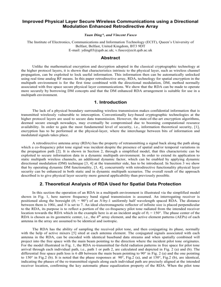
Improved Physical Layer Secure Wireless Communications using a Directional Modulation Enhanced Retrodirective Array Yuan Ding*, and Vincent Fusco The Institute of Electronics, Communications and Information Technology (ECIT), Queen’s University of Belfast, Belfast, United Kingdom, BT3 9DT E-mail: yding03@qub.ac.uk; v.fusco@ecit.qub.ac.uk Abstract Unlike the mathematical encryption and decryption adopted in the classical cryptographic technology at the higher protocol layers, it is shown that characteristics intrinsic to the physical layer, such as wireless channel propagation, can be exploited to lock useful information. This information then can be automatically unlocked using real time analog RF means. In this paper retrodirective array, RDA, technology for spatial encryption in the multipath environment is for the first time combined with the directional modulation, DM, method normally associated with free space secure physical layer communications. We show that the RDA can be made to operate more securely by borrowing DM concepts and that the DM enhanced RDA arrangement is suitable for use in a multipath environment. 1. Introduction The lack of a physical boundary surrounding wireless transmission makes confidential information that is transmitted wirelessly vulnerable to interception. Conventionally key-based cryptographic technologies at the higher protocol layers are used to secure data transmission. However, the state-of-the-art encryption algorithms, deemed secure enough nowadays, may eventually be compromised due to booming computational resource availability. In order to gain the most fundamental level of security, i.e., information theoretical security, [1], encryption has to be performed at the physical-layer, where the interchange between bits of information and modulated signals takes place. A retrodirective antenna array (RDA) has the property of retransmitting a signal back along the path along which a co-frequency pilot tone signal was incident despite the presence of spatial and/or temporal variations in the propagation path [2]. It is shown in Section 2, through a simplified model, that this characteristic can be exploited to secure information data in a dynamic multipath environment. In order to extend its application to static multipath wireless channels, an additional dynamic factor, which can be enabled by applying dynamic directional modulation (DM) technique [3, 4] at the transmitter side, has to be introduced. In Section 3 we show that by operating dynamic DM functionality, [3, 4], concurrently with retrodirective functionality physical layer security can be enhanced in both static and in dynamic multipath scenarios. The overall result of the approach described is to give physical layer security more general applicability than previously possible. 2. Theoretical Analysis of RDA Used for Spatial Data Protection In this section the operation of an RDA in a multipath environment is illustrated via the simplified model shown in Fig. 1, here narrow frequency band signal transmission is assumed. An interrogating receiver is positioned along the boresight (θ1 = 90°) of an N-by-1 uniformly half wavelength spaced RDA. The distance between them is 100λ, and N is set to 7. An ideal electromagnetic reflector of infinite size is placed perpendicular to the RDA, its purpose is to reflect a portion of the co-frequency pilot tone radiated from the intended receiver location towards the RDA which in the example here is at an incident angle of θ2 = 150°. The phase center of the RDA is chosen as its geometric center, i.e., the 4th array element, and the active element patterns (AEPs) of each antenna in the array are assumed to be identical and isotropic. The RDA has the ability of sampling the received pilot tone, and then conjugating its phase, normally with the help of active mixers [5] sited at each antenna element. The conjugated signals associated with each antenna in the RDA, can be encoded with identical baseband data streams and when spatially combined will project into the free space with the main beam pointing to the direction where the incident pilot tone originates. For the model illustrated in Fig. 1, the RDA re-transmitted far-field radiation patterns in free space for pilot tone arrival through each individual path, i.e., path 1 or path 2, are calculated and depicted in Fig. 2 (a) and (b). The differential free space path loss is 6 dB between the main beam pointing to 90° in Fig. 2 (a) and the one pointing to 150° in Fig.2 (b). It is noted that the phase responses at 90°, Fig.2 (a), and at 150°, Fig.2 (b), are identical, indicating the phases of the re-transmitted signals along each individual path are precisely aligned at the intended receiver location, confirming the key automatic phase equalization property of the RDA. When the pilot tone arrives at the RDA from θ1 and θ2 simultaneously, the re-transmitted far-field pattern in free space is altered into the one shown in Fig. 2 (c). This pattern can either be obtained by summing the pilot tones arriving from each path, phase conjugating, and then generating the far-field pattern, or, by vectorially combining the far-field patterns in (a) and (b), both methods are equivalent. Reflector Path 2 Retrodirective Array ele. 1 λ/2 ele. 2 ele. 3 ……… Phase Center ele. N-1 Path 1 θ2=150˚ Intended Receiver Pilot Tone 100λ θ1=90˚ ele. N Figure 1. A two-ray model of an N-by-1 RDA. 3 3 0 90º −10 0º −20 −90º 3 90º 0 0 90º −10 0º −20 −90º 30º 60º 90º 120º Spatial Direction θ 150º −180º 180º −90º −30 0º 30º 60º 90º 120º Spatial Direction θ (a) 150º −180º 180º Magnitude (dB) Magnitude (dB) −20 Phase −30 0º 0º Phase Phase Magnitude (dB) −6 −10 −30 0º 30º 60º 90º 120º Spatial Direction θ (b) 150º −180º 180º (c) Figure 2. RDA re-transmitted far-field patterns (a) when the pilot tone arrives only via path 1, (b) when the pilot tone arrives only via path 2, (c) when the pilot tone arrives simultaneously via both path 1 and path 2. To illustrate representative signal quality at the receiver side, the combined electric fields, one retransmitted along line-of-sight and the other along the reflected path, at a constant distance in the far field of 100λ are computed and presented in Fig. 3. It is noted that the pilot tone is fixed along the boresight shown in Fig. 1. It can be observed in Fig. 3 that far field electric field spatial distribution fluctuates dramatically outside of the small region around the pilot tone transmission position. In other words the detected signals at these undesignated locations are very sensitive to the environment. If the wireless channel alters a little, the received signals in those locations can suffer significant changes or deep fading. Whereas the received signal around the pilot tone location is much less sensitive since, at this location the RDA has the ability to re-construct the signals from different wireless paths in-phase. This property of the RDA gives the receiver at the pilot tone location significant advantage, with regards to information recovery, over receivers positioned anywhere else in the multipath environment. Thus a physical-layer security system can be constructed based on the RDA in dynamic multipath environment. On the other hand if the wireless environment contains multipath which is static then modulation constellations transported by the RDA on re-transmission will be all offset by the same differential phase shift as was present in the original modulation and scaled in magnitude. Thus in principle a suitable receiver could recover data everywhere where the RDA is projecting far field radiation. 3 180º 0 135º −10 45º Phase Magnitude (dB) 90º 0º −45º −20 −90º −135º −30 0º 30º 60º 90º 120º Spatial Direction θ 150º 180º −180º 0º 30º 60º 90º 120º 150º 180º Spatial Direction θ (a) (b) Figure 3. Normalized electric field, (a) magnitude and (b) phase, at a distance of 100λ w.r.t. RDA along spatial directions from 0° to 150°. 3. Directional Modulation Enhanced RDA With regards to the secrecy performance, it has been previously shown that the RDA works best in dynamic multipath-rich environments [2]. In order to extend RDA application into a static multipath wireless channel scenario, the DM concept, [3], can be borrowed to enable and enhance RDA secrecy performance. Generally speaking, DM is a transmitter side technology that is able to distort transmitted signal constellation patterns in IQ space along all spatial directions other than along an a-priori selected secured communication direction, in free space, in such a fashion to reduce the probability of interception by potential eavesdroppers [3, 4]. We now apply the DM technique onto the RDA in a static multipath environment. Using the two path model in Fig. 1, the normalized channel vector H between the RDA and the intended receiver can be obtained and is written in (1). H 0.331e j 0.512 0.471e j 0.273 0.198e j 0.360 0.471e j 0.273 0.510 0.198e j 0.360 0.331e j 0.512 (1) Each element in H is the pilot tone signal detected by each antenna in the RDA, subject to an identical scaling factor. Similar to the orthogonal vector concept proposed in [3] for DM, an infinite number of vectors can be generated in the null space of H . These vectors are termed orthogonal vectors, H ov , hereafter. After the orthogonal vectors are generated, they can be combined with the phase conjugation output of a conventional RDA, i.e., H . ‘*’ is the complex conjugation operator. Dm H H ov H = Dm H H H ov H Dm H 2 (2) In (2) it is noted that the transmitted information data, Dm for the mth symbol, can be readily recovered by a receiver at the pilot tone location, since the detected signals at this location are unaffected by the artificially injected vector H ov , i.e., H ov H = 0 . However, for receivers at other positions, the channel vector H becomes G , and H ov and G are not orthogonal. Thus the detected signals Sm are additionally corrupted by this artificially injected interference H ov at locations away from the pilot tone location, see (3). Sm Dm H Hov G = Dm H G Hov G (3) Fig. 4 illustrates electric fields examples at the distance of 100λ when four unique QPSK symbols are transmitted. The injected orthogonal vectors associated with each QPSK symbol are listed in Table 1. To increase graph readability, the spatial resolution of the curves in Fig. 4 is reduced by 5 times that in Fig. 3. It can be seen in Fig. 4 that only at the pilot tone location the magnitudes of the four QPSK symbols overlap each other, and their phases are 90° spaced, indicating that a standard QPSK constellation, i.e., a central symmetric square in IQ space, is formed. The constellation patterns detected in all other locations are scrambled. This functionality cannot be achieved by a conventional RDA in a purely static multipath wireless channel, for narrow frequency band signal transmission. 3 180º 0 135º 45º Phase Magnitude (dB) 90º −10 For Symbol ‘11’ 0º For Symbol ‘01’ −45º −20 For Symbol ‘00’ −90º −135º −30 0º 30º 60º 90º 120º Spatial Direction θ (a) 150º 180º −180º For Symbol ‘10’ 0º 30º 60º 90º 120º 150º 180º Spatial Direction θ (b) Figure 4. Normalized electric fields, (a) magnitudes and (b) phases, at a distance of 100λ w.r.t. the RDA along spatial directions from 0° to 150° for each unique QPSK symbol transmitted. The injected orthogonal vectors are as listed in Table 1. −1 a H ov (×10 ) Symbol ‘11’ Symbol ‘01’ Symbol ‘00’ Symbol ‘10’ Table 1. Orthogonal vectors associated with each unique QPSK symbol shown in Figure 4, static two ray case. Hov1 Hov2 Hov3 Hov4 Hov5 Hov6 Hov7 −3.366−j1.386 1.613+j0.010 0.106−j0.324 0.371−j0.375 0.349+j0.052 0.209 −j0.676 0.852+j0.226 −2.519−j1.248 −0.175−j0.063 0.308−j0.274 −0.194−j0.363 1.196+j0.010 0.323−j0.582 2.736+j0.126 −2.326−j1.155 −0.559−j0.059 0.705−j0.253 0.328−j0.336 2.222+j0.009 −0.247−j0.538 2.125+j0.116 −2.218−j0.141 −0.473+j0.264 2.970−j0.099 −0.666+j0.054 0.037+j0.138 1.732−j0.169 −0.009+j0.307 Hov7 a. Hov Hov1 Hov2 When the H ov vector is randomly and dynamically selected with regards to the each symbol in a data stream, the received signals, mapped into constellation patterns in IQ space, at undesignated locations are randomly and dynamically updated during the whole transmission process, thus imposing a greater challenge to eavesdroppers. This is verified by bit error rate simulations in the distance region from 90 λ to 200λ, see Fig. 5. Here a signal to noise ratio (SNR) of 23 dB at the intended receiver location is assumed, and the AWGN contribution is identical over the entire simulated area. A data stream with 106 random QPSK symbols is used for BER simulations. Specific details on BER calculation method can be found in [4]. In Fig. 5 it is observed that the additional DM functionality has the ability of shrinking the error free area around the pilot tone location and suppressing BER sidelobes elsewhere. This enhancement would be much greater in a highly multipath rich environment. 200 200 100 SNR=23 dB DM Enabled 90º 120º 150º 10–4 120 10–5 100 180º 90 Distance (λ) 10–2 a 10–3 10–4 Intended Receiver 0º 30º Spatial Direction θ 60º 90º BER 60º 140 10–1 None Simulation Zone 30º 160 Error Free Zone 0º 10–2 a 10–3 Intended Receiver 100 180 BER 120 90 None Simulation Zone Error Free Zone 140 10–1 Distance (λ) 180 160 100 SNR=23 dB DM Disabled 10–5 120º 150º 180º Spatial Direction θ (a) (b) Figure 5. Static two ray model BER simulation results in far-field areas (a) without and (b) with DM functionalities. SNR at the intended receiver location is set to 23 dB. 4. Conclusion In this paper two techniques, RDA (which adds physical layer security in dynamic multipath environments) and DM (which adds physical layer security in multipath free environments), were combined to result in a DM enhanced RDA, which can provide physical layer information theoretical security under static as well as dynamic multipath wireless channel conditions. When used alone or in-conjunction with data that has been encrypted by conventional mathematical means, the system described in the paper should lead to an extremely high degree of data protection from unwanted interception. 5. Acknowledgments This work was sponsored by the Queen’s University of Belfast High Frequency Research Scholarship. 6. References 1. M. Bloch and J. Barros, Physical-Layer Security from Information Theory to Security Engineering, Cambridge University Press, Oct. 2011. 2. V. F. Fusco and N. B. Buchanan, “Retrodirective Antenna Spatial Data Protection,” IEEE Antennas Wireless Propag. Lett., vol. 8, pp. 490-493, 2009. 3. Y. Ding and V. Fusco, “A Vector Approach for the Analysis and Synthesis of Directional Modulation Transmitters,” IEEE Trans. Antennas Propagat., vol. 62, no. 1, pp. 361-370, Jan. 2014. 4. Y. Ding and V. Fusco, “Establishing Metrics for Assessing the Performance of Directional Modulation Systems” IEEE Trans. Antennas Propagat., in press. 5. C. Y. Pon, “Retrodirective Array using Heterodyne Technique,” IEEE Trans. Antennas Propagat., vol. 12, no. 1, pp. 176-180, Jan. 1964.


