SWITCHBLADE Beaver Readme THE AIRCRAFT This is a replica of
advertisement

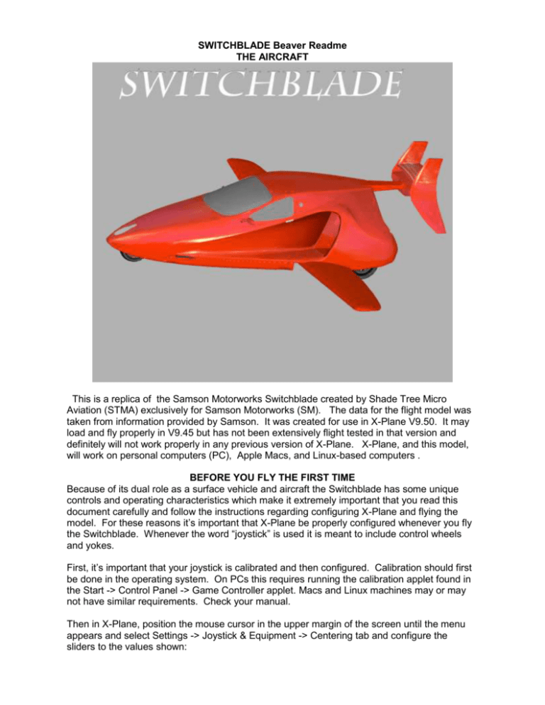
SWITCHBLADE Beaver Readme THE AIRCRAFT This is a replica of the Samson Motorworks Switchblade created by Shade Tree Micro Aviation (STMA) exclusively for Samson Motorworks (SM). The data for the flight model was taken from information provided by Samson. It was created for use in X-Plane V9.50. It may load and fly properly in V9.45 but has not been extensively flight tested in that version and definitely will not work properly in any previous version of X-Plane. X-Plane, and this model, will work on personal computers (PC), Apple Macs, and Linux-based computers . BEFORE YOU FLY THE FIRST TIME Because of its dual role as a surface vehicle and aircraft the Switchblade has some unique controls and operating characteristics which make it extremely important that you read this document carefully and follow the instructions regarding configuring X-Plane and flying the model. For these reasons it’s important that X-Plane be properly configured whenever you fly the Switchblade. Whenever the word “joystick” is used it is meant to include control wheels and yokes. First, it’s important that your joystick is calibrated and then configured. Calibration should first be done in the operating system. On PCs this requires running the calibration applet found in the Start -> Control Panel -> Game Controller applet. Macs and Linux machines may or may not have similar requirements. Check your manual. Then in X-Plane, position the mouse cursor in the upper margin of the screen until the menu appears and select Settings -> Joystick & Equipment -> Centering tab and configure the sliders to the values shown: Experience has shown that these approximate values provide the most realistic “feel” to most retail joysticks but you can adjust to suit your desires after gaining experience. Next, the joystick axes needs to be configured by following these steps: 1) Move the joystick from side to side. This is the roll axis. Note which slider moves back and forth in time to the joystick movement. Click on the drop-down list immediately to the left of that line and click on “roll” with the mouse cursor. 2) Move the joystick forward and aft. This is the pitch axis. Note which slider moves with the joystick, click on the list and click to select “pitch”. 3) If your joystick has an available slider or rotary switch assign it to the elevator trim using the above procedure. If it doesn’t elevator trim can be set by using the keyboard “[“ and “]” keys or by clicking on the elevator trim wheel displayed on the instrument panel. 4) If the joystick has an associated throttle quadrant or more available sliders or rotary switch, repeat the above procedure for the throttle (F1/F2), prop (F5/F6), and mixture (F9/F10), and rudder trim (9/0). If not, click and move the appropriate control on the instrument panel or click on the keyboard shortcuts listed for each control. 5) When all desired controls are assigned, click on the Calibrate Joystick Hardware button and follow the displayed instructions. Brakes are normally applied by applying pressure on the tips of the rudder pedals (if available), by clicking on the “Brakes” light located in the upper center of the instrument panel, or by pressing the keyboard “b” key. In order to approximate the enhanced braking action available in the Switchblade, assign a joystick button as follows. 1) Go to the Buttons: Basic tab and click on any unassigned joystick button. How do you know that it’s unassigned? The little “radio button” green dot will stay in the “do nothing at all!” circle. 2) Position the mouse cursor in the “Toggle brakes maximum effort” circle and click. The green dot should appear in that circle. 3) Confirm that the button is set by clicking on any other button to move the green dot and then click your selected brakes button. The dot should move back to the Toggle brakes maximum effort circle. LIVERIES (SKINS) This model currently comes with the default SM red skin. Other skins may be added in the future. Click on Aircraft -> Open Livery and click on the appropriate radio button to select and display the desired skin from any available. In V9.3x and up any skin selected in Plane-Maker and saved will display as the default skin until you change and save it again in Plane-Maker. Users are encouraged to create their own skins and may freely distribute those skins as long as they don't require modification to or distribution of the switchblade.acf or any associated files, which are all copyrighted by SM. Although we prefer that each customer creates new texture files, the following texture files may be customer modified when creating a skin fuselage.png, interior.png, and glass.png. If modified files are used, SM must be given proper attribution as the source of the files. As long as you stay within the texture layout areas on each of the current texture files your new skins will display properly. Contact STMA at the addresses shown on the shadetreemicro.com contact page and we’ll be happy to help you with our project. 3D OBJECT VIEWING This model comes with and loads directly into the 2D instrument panel. There is a prototype 3D cockpit included. It is not functional at this time. If you desire seeing how the 3D Cockpit currently looks press CTRL+o or set a joystick switch to “Toggle 3D Cockpit.” VIEWING TIPS This model has an enhanced instrument panel, which is configured so that the most important controls on the panel are visible by default. To see the very upper edge of the windshield, press the up arrow key. To see the bottom of the instrument panel, press the down arrow key. We recommend setting the X-Plane screen resolution to at least 1024x1024 for best viewing. 1280x1024 pixels works really well. The graphic used for the instrument panel is 1024x 1024 pixels so a screen resolution equal to that or larger will show the entire panel. If using a widescreen monitor and selecting an instrument panel resolution wider than 1024 pixels you will need to adjust the field of view in X-Plane’s rendering options menu (Settings -> Rendering Options) to a value between 45 to 75 degrees or slightly more in order to achieve the panel view that fits your flying style. CLICKABLE CONTROLS & CONTROL DESCRIPTIONS Clickable regions can be found by hovering the mouse over and around a suspected clickable area. If one is found the mouse pointer will change shape. To see which of the buttons, knobs, etc., are clickable clicking on Aircraft ->Show Mouse-Click Regions. Yellow boxes will appear surrounding all clickable controls. Clicking on Aircraft -> Show Instrument Descriptions will display tooltip text describing the operation of the selected control when the mouse cursor is hovered over the control. OPERATING TIPS AND CONTROL USAGE The Instrument Panel Layout: The panel consists of 2 Dynon SkyView panels with associated switches. NOTE: These instruments are X-Plane’s interpretation of the SkyView system and are NOT representative of the features available on the real panels. We are providing the displays only so users can get a basic feel for the way the real panel will look and work. The Primary Flight Display (PFD) displays: Airspeed: Shown in the black box and scale to the left of the attitude indicator. A colored tape to its right shows the speed limits. Altitude: Shown in the black box and scale to the right of the attitude indicator. Vertical Velocity: Shown by the scale and pointer to the right of the altitude indicator. Navigation Information: Shown in the right half of the display with various display features controlled by the buttons in the lower bezel. The compass rose’s shape and range is set by the buttons underneath the attitude indicator, while the source for the navigation needles is set by the Nav Source button located immediately under the Angle of Attack (AOA) indicator. Flight Director Command Bars: Controlled by the lower leftmost button. The Multi-Function Display (MFD) displays: HITS (Highway In the Sky): This is a fanciful feature not present on the real unit, which will display, among other things, a moving map with navigation and weather overlays, etc. Engine Function Panel: The primary display shows engine power and health indicators as follows: Upper left: manifold pressure. Upper right: engine/prop RPM. Lower left: cylinder temperature Lower right: fuel flow. Detailed pages of information are available through the buttons in the lower bezel. The Flaps: Use 15 degrees (1 notch) of flaps for all takeoffs. The current flap position is shown by the position of the flap handle and by a flap indicator in the lower right corner of the PFD. TRIM: The Elevator and Rudder Trim wheels are located on the center pedestal to the right of the flaps and sweeps controls. Indicators are adjacent to their respective wheels. Elevator trim should be set one index mark (in the nose up direction) below the center position for takeoff. Take-offs and Landings: Should always be made as much into the wind as is possible. You may not get airborne if a downwind take-off is attempted. The following takeoff procedure has been found to work well: 1) Make sure the gear handle is down, which raises the nose of the Switchblade 5°. 2) Make sure the wings and empennage (tail) is locked into the flight position (Sweep handle UP). 3) Set trim one index mark below the center position. 4) Set 15° flaps. 5) Hold aileron (lateral yoke control) into the wind. The Switchblade does not have rudder pedals. The control wheel interconnects with the nosewheel and rudders to provide directional control on the ground. A crosswind will try to push the Switchblade downwind so aileron control is needed to stop the drift and keep the ‘blade pointed down the runway. 6) Smoothly add full power, using the control wheel to keep the aircraft going straight. 7) Passing 75 knots gently increase control wheel back pressure until the nosewheel lifts of the ground. A small increase of elevator trim may aid this process (this is where having the elevator trim assigned to a rotary switch on the joystick really helps). 8) Once airborne and climbing retract the flaps (lever full up) before reaching 100 knots. 9) Apply elevator and rudder trim as needed to relieve control pressures. Landings are conventional and can be made with flaps up or down and with the landing gear up or down. Performance Charts: Will be provided by Samson Motorworks. LEGAL STUFF © (copyright) July 2010 by Samson Motorworks. This aircraft model and all associated files requires X-Plane flight simulation software by Laminar Research to be functional and is subject to X-Plane's user's agreement and licensing. This model is payware. Do not use it for any commercial purpose or distribute it by any means without permission of the authors. For commercial licensing, or if you desire to alter it for your personal use, send an e-mail to Shade Tree Micro Aviation at papamac@sbcglobal.net. This model is believed to be defect free but is offered without warranty, either express or implied.


