27: Current in a Magnetic Field
Chapter 27: Current in a Magnetic Field
Please remember to photocopy 4 pages onto one sheet by going A3→A4 and using back to back on the photocopier.
A Current-carrying Conductor in a Magnetic Field experiences a Force
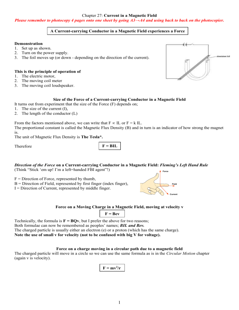
Demonstration
1.
Set up as shown.
2.
Turn on the power supply.
3.
The foil moves up (or down - depending on the direction of the current).
This is the principle of operation of
1.
The electric motor,
2.
The moving coil meter
3.
The moving coil loudspeaker.
Size of the Force of a Current-carrying Conductor in a Magnetic Field
It turns out from experiment that the size of the Force (F) depends on;
1.
The size of the current (I),
2.
The length of the conductor (L)
From the factors mentioned above, we can write that F
IL or F = k IL.
The proportional constant is called the Magnetic Flux Density (B) and in turn is an indicator of how strong the magnet is.
The unit of Magnetic Flux Density is The Tesla*.
Therefore F = BIL
Direction of the Force on a Current-carrying Conductor in a Magnetic Field: Fleming’s Left Hand Rule
(Think “Stick ‘em up! I’m a left=handed FBI agent”!)
F = Direction of Force, represented by thumb,
B = Direction of Field, represented by first finger (index finger),
I = Direction of Current, represented by middle finger.
Force
Field
Current
Force on a Moving Charge in a Magnetic Field, moving at velocity v
F = Bev
Technically, the formula is F = BQv , but I prefer the above for two reasons;
Both formulae can now be remembered as peoples’ names; BIL and Bev.
The charged particle is usually either an electron (e) or a proton (which has the same charge).
Note the use of small v for velocity (not to be confused with big V for voltage).
Force on a charge moving in a circular path due to a magnetic field
The charged particle will move in a circle so we can use the same formula as is in the Circular Motion chapter
(again v is velocity).
F = mv 2 /r
1
Derivation of the Formula F = Bqv l
Consider a section of conductor of length l through which a current I is flowing.
If q is the charge which carries the current in this section of the conductor, then:
I = q/t , (remember q = It ( Q u IT ?) where t is the time it takes the charge q to travel a distance l) .
The average velocity with which the charge flows is given by v = l / t , i.e. l = vt .
Substituting into the primary equation which we have for force (F = BIL), we get
F = B × q/t × vt i.e. F = Bqv
The Magnetic Force between Two Current-carrying Conductors
Two current carrying conductors will exert a force on each other.
This is the principle on which the definition of the ampere is based.
The Ampere
*
The ampere is the amount of charge which, if flowing in (1) two (2) very long (3) parallel wires (4) one metre apart (5) in a vacuum (6) will experience a force of 2 x 10 -7 N per metre length.
To demonstrate the principle on which the definition of the ampere is based
1.
Connect two conductors (aluminium strips will do nicely) up to two separate power supplies such that you have two circuits containing the parallel strips side by side.
2.
Complete the circuit to switch on the current.
3.
The strips will either move towards each other or repel each other, depending on the direction of the currents.
Leaving Cert Physics Syllabus
Content
3. Current in a magnetic field
Depth of Treatment
Current-carrying conductor experiences a force in a magnetic field.
Direction of the force.
Force depends on
• the current
• the length of the wire
• the strength of the magnetic field.
F
I l B
Magnetic flux density B = F/IL
Derivation of F = qvB
Forces between currents
(non-mathematical treatment).
Definition of the ampere.
Activities
Demonstration of the force on a conductor and coil in a magnetic field.
Appropriate calculations.
Appropriate calculations.
STS
Applications in motors, meters, and loudspeakers.
2
Extra Credit
*The Tesla
Check out this dude Tesla on the web – he’s a cult figure – straight out of The X-Files
Inventions:
A telephone repeater, rotating magnetic field principle, polyphase alternating-current system, induction motor, alternating-current power transmission, Tesla coil transformer, wireless communication, radio, fluorescent lights, and more than 700 other patents.
I have two books on Tesla available here in A7 – ask and you shall receive.
By the way, can you remember where we came across this guy before?
Hint: He was a big into resonance.
Bigger hint: Mechanical hammer and a wall.
*Ampere
In his early years, Ampere saw the sway of the reign of terror following the French Revolution.
He witnessed as a boy the murder of his father in 1789 when every titled person was subject to execution or imprisonment. Trauma of this tragedy, followed by his wife's death in 1803, made him an embittered person, spending his time as an introvert. Perhaps, it was this introversion that spurred him to pursue electricity and magnetism where his contributions earned him an immortal place in history of science, and a name that is synonymous with what is quite possibly the nastiest definition on the Leaving Cert Physics syllabus.
3
Exam Questions ( Charge on an electron = 1.6 × 10
–19
C)
1.
[2006 OL]
The diagram shows an experiment to demonstrate that a current-carrying conductor experiences a force in a magnetic field. A strip of aluminium foil is placed at right angles to a U-shaped magnet. The foil is connected in series with a battery and a switch.
When the switch is closed the aluminium foil experiences an upward force.
(i) Describe what will happen if the current flows in the opposite direction.
(ii) Describe what will happen if a larger current flows through the aluminium foil.
(iii) Describe what will happen if the aluminium foil is placed parallel to the magnetic field.
2.
[2003 OL]
(i) In an experiment, a thin light conductor is placed between the poles of a U-shaped magnet as shown in the diagram. Describe what happens when a current flows through the conductor.
(ii) What would happen if a larger current flowed in the conductor?
(iii) What would happen if the current flowed in the opposite direction through the conductor?
3.
[2009 OL]
The diagram shows a compass placed near a wire connected to a battery and a switch.
(i) Why happens to the compass when the switch is closed?
(ii) What does this tell you about an electric current?
(iii) What happens to the compass when the switch is opened?
(iv) The wire is then placed between the poles of a U-shaped magnet, as shown in the diagram.
Describe what happens to the wire when a current flows through it.
(v) What would happen if the current flowed in the opposite direction?
(vi) Name two devices that are based on this effect.
4.
[2002][2002 OL][2005 OL]
A current-carrying conductor experiences a force when placed in a magnetic field. Name two factors that affect the magnitude of the force.
5.
[2002 OL][2002 OL][2006 OL]
Name two devices that are based on the principle that a current-carrying conductor in a magnetic field experiences a force.
6.
[2007]
State the principle on which the definition of the ampere is based.
7.
[2002 OL][2005 OL]
Describe an experiment to demonstrate that a current-carrying conductor in a magnetic field experiences a force.
8.
[2006][2003]
Describe an experiment to demonstrate the principle on which the definition of the ampere is based.
9.
[2006][2003]
Define the ampere, the SI unit of current.
10.
[2006 OL]
Calculate the force on the aluminium foil if its length is 10 cm and a current of 1.5 A flows through it when it is placed in a magnetic field of flux density 3.0 T.
11.
[2004 OL]
A conductor of length 50 cm is carrying a current of 5 A. It is placed at right angles to a magnetic field of flux density 3 T. Calculate the force on the conductor.
4
12.
[2003]
Give an expression for the force acting on a charge q moving at a velocity v at right angles to a magnetic field of flux density B .
13.
[2003]
(i) The electron travels at a constant speed of 3.75 × 10 7 m s deflected. The flux density of the magnetic field is 5 × 10
-1
–2
and enters a magnetic field at right angles, where it is
T.
Calculate the force acting on the electron.
(ii) Calculate the radius of the circular path followed by the electron, in the magnetic field.
14.
[2010 OL]
Read this passage and answer the questions below.
In 1819 the Danish physicist Hans Christian Oersted discovered that an electric current flowing through a wire deflected a compass needle.
A year later the Frenchman François Arago found that a wire carrying an electric current acted as a magnet and could attract iron filings. Soon his compatriot André-Marie Ampère demonstrated that two parallel wires were attracted towards one another if each had a current flowing through it in the same direction. However, the wires repelled each other if the currents flowed in the opposite directions.
Intrigued by the fact that a flow of electricity could create magnetism, the great British experimentalist
Michael Faraday decided to see if he could generate electricity using magnetism. He pushed a bar magnet in and out of a coil of wire and found an electric current being generated. The current stopped whenever the magnet was motionless within the coil.
(Adapted from ‘
Quantum' by Manjit Kumar, Icon Books 2008 )
(i) Who discovered that an electric current can deflect a compass needle?
(ii) What did Arago discover?
(iii)What happens when currents flow in the same direction in two parallel wires?
(iv) How could two parallel wires be made to repel each other?
5
Exam Solutions
1.
(i) The aluminium foil will move in the opposite direction.
(ii) The foil will experience a greater force and therefore there will be a greater jump.
(iii) Nothing will happen because they have to be at an angle to each other.
2.
(i) The conductor experiences a force and deflects.
(ii) A bigger deflection .
(iii) The conductor would deflect in the opposite direction.
3.
(i) The needle moves (deflects)
(ii) It has a magnetic effect.
(iii) The needle returns to its original position.
(iv) The wire deflects (and gets hot).
(v) The wire moves in the opposite direction (because the magnetic field reverses).
(vi) Electric motors and loudspeakers.
4.
Strength of magnetic field, size of current flowing, length of conductor in magnetic field.
5.
Motor, galvanometer, loudspeaker.
6.
A current-carrying conductor in a magnetic field experiences a force.
7.
Set up as shown.
Turn on the power supply.
The foil moves up (or down - depending on the direction of the current).
8.
Power supply, two aluminium foil strips
Some means of keeping strips parallel
Switch on current
Strips move
9.
The ampere is the amount of charge which, if flowing in two very long parallel wires one metre apart in a vacuum will experience a force of 2 × 10 -7 N per metre length.
10.
F = B I l
F = 3 × 1.5 × 0.1 = 0.45 N.
11.
F = B I l
F = 3 × 5 × 0.5 = 7.5 N
12.
F = Bqv
13.
(i) F = Bev = (5 × 10
–2
(ii) F = mv 2 /r
r = 4.3×10
−3 m
)(1.6 × 10
–19
)( 3.75 × 10
3.0 ×10
−13
7 )
= (9.1 × 10
–31
= 3.0 ×10
)( 3.75 × 10 7 ) 2 /r
−13
N
14.
(i) Hans Oersted
(ii) A wire carrying an electric current acted as a magnet could attract iron filings.
(iii)The wires attract
(iv) Reverse one of the currents / current in opposite directions
6


