Alignment Document
advertisement
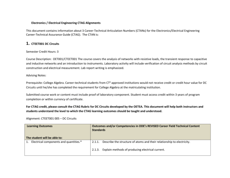
Electronics / Electrical Engineering CTAG Alignments This document contains information about 3 Career-Technical Articulation Numbers (CTANs) for the Electronics/Electrical Engineering Career-Technical Assurance Guide (CTAG). The CTAN is: 1. CTEET001 DC Circuits Semester Credit Hours: 3 Course Description: OET001/CTEET001 The course covers the analysis of networks with resistive loads, the transient response to capacitive and inductive networks and an introduction to instruments. Laboratory activity will include verification of circuit analysis methods by circuit construction and electrical measurement. Lab report writing is emphasized. Advising Notes: Prerequisite: College Algebra. Career-technical students from CT² approved institutions would not receive credit or credit hour value for DC Circuits until he/she has completed the requirement for College Algebra at the matriculating institution. Submitted course work or content must include proof of laboratory component. Student must access credit within 3 years of program completion or within currency of certificate. For CTAG credit, please consult the CTAG Rubric for DC Circuits developed by the OETEA. This document will help both instructors and students understand the level to which the CTAG learning outcomes should be taught and understood. Alignment: CTEET001 005 – DC Circuits Learning Outcomes The student will be able to: 1. Electrical components and quantities.* Outcomes and/or Competencies in ODE’s REVISED Career Field Technical Content Standards 2.1.1. Describe the structure of atoms and their relationship to electricity. 2.1.3. Explain methods of producing electrical current. 2.1.4. Explain how batteries store and disperse energy. 2.1.5. Compare and contrast alternating current (AC) and direct current (DC). 2.4.1. Identify resistor values from color codes or other marks. 2.4.2. Compare and contrast resistor compositions and their uses. 2. Definitions of voltage, current, electrical resistance and power.* 2.4.3. Identify symbols for electronic components. 2.1.3. Explain methods of producing electrical current. 2.1.4. Explain how batteries store and disperse energy. 2.1.5. Compare and contrast alternating current (AC) and direct current (DC). 2.1.6. Define the units of measurement for voltage, current, power, and resistance. 3. Ohm’s Law, electrical energy and power, Kirchhoff’s Laws.* 4. Series circuit analysis.* 2.1.7. Describe the relationships between voltage, current, resistance, and power in circuits. 2.1.8. Determine voltage, current, resistance, and power in circuits using Ohm’s Law, Kirchhoff’s Law, and Watt’s Law. 2.1.8. Determine voltage, current, resistance, and power in circuits using Ohm’s Law, Kirchhoff’s Law, and Watt’s Law. 2.2.8. Explain the uses of series, parallel, and series-parallel circuits. 5. Parallel circuit analysis.* 2.2.9. Construct and troubleshoot series, parallel, and series-parallel circuits. 2.1.8. Determine voltage, current, resistance, and power in circuits using Ohm’s Law, Kirchhoff’s Law, and Watt’s Law. 2.2.8. Explain the uses of series, parallel, and series-parallel circuits. 2.2.9. Construct and troubleshoot series, parallel, and series-parallel circuits. 6. Series-parallel circuit analysis.* 2.1.8. Determine voltage, current, resistance, and power in circuits using Ohm’s Law, Kirchhoff’s Law, and Watt’s Law. 2.2.8. Explain the uses of series, parallel, and series-parallel circuits. 7. Circuit theorems (such as superposition, Thevenin’s and Norton’s theorems).* 8. Mesh and/or nodal analysis techniques.* 9. Properties of capacitors and their behavior under DC conditions.* 2.2.9. Construct and troubleshoot series, parallel, and series-parallel circuits. 2.1.8. Determine voltage, current, resistance, and power in circuits using Ohm’s Law, Kirchhoff’s Law, and Watt’s Law. 2.1.8. Determine voltage, current, resistance, and power in circuits using Ohm’s Law, Kirchhoff’s Law, and Watt’s Law. 2.1.11. Identify methods of varying capacitance. 2.2.5. Identify types of capacitors and common usages for each. 10. Properties of inductors and their behavior 2.2.7. Identify the function of inductors and capacitors in series and parallel circuits. under DC conditions.* *Learning Outcomes with an asterisk are essential and must be taught. 2. CTEET002 – Digital Electronics: CTAN alignment with the Tech Prep Manufacturing Production Pathway in the Career Field Technical Content Standards of the Ohio Department of Education. This CTAN is already an approved CTAN in the Electrical Engineering Technology CTAG. The number and title are: CTEET002 – Digital Electronics. Semester Credit Hours: 4 Advising Notes: Submitted course work must include proof of laboratory component For CTAG credit, please consult the TAG Rubric for Digital Electronics developed by the OETEA. This document will help both instructors and students understand the level to which the CTAG learning outcomes should be taught and understood. Course Description: Digital Electronics OET002/CTEET002: Introduces students to computer based number systems, symbolic logic concepts, Boolean Algebra, logic devices, and basic logic circuits. Logic circuits are analyzed using truth tables and timing diagrams. Laboratory work will demonstrate and verify the principles studied in the classroom. Alignment: Learning Outcomes The student will be able to: 1. Number Systems, operations and codes* Outcomes and/or Competencies in ODE’s REVISED Career Field Technical Content Standards 2.6 Digital Electronics: Create circuits to perform tasks and operations. 2.6.10 Identify the numbering systems, codes, arithmetic operations, Boolean operations, and simplification methods used in digital electronics. 2. Logic Gates* 2.6.2. Describe the purpose and use of logic gates (e.g., discrete and medium scale integration [MSI] gates, latches, flip-flops). 3. Boolean algebra* 2.6.10. Identify the numbering systems, codes, arithmetic operations, Boolean operations, and simplification methods used in digital electronics. 4. DeMorgan’s theorem and logic simplification* 2.6.2. Describe the purpose and use of logic gates (e.g., discrete and medium scale integration [MSI] gates, latches, flip-flops). 2.6.10 Identify the numbering systems, codes, arithmetic operations, Boolean operations, and simplification methods used in digital electronics. 5. Combination logic circuits* 6. Encoders / decoders* 2.6.18 Use the Boolean Algebra laws and DeMorgan’s Theorem in the simplification of logic circuits. 2.6.3. Design a paradigm for combinational logic problems (i.e., encoders, decoders, multiplexers, demultiplexers, adders, subtractors, ALUs). 2.6.3 Design a paradigm for combinational logic problems (i.e., encoders, decoders, multiplexers, demultiplexers, adders, subtractors, ALUs). 2.6.4. Design a specific MSI gate application 7. 8. Multiplexers / demultiplexers* Adders, subtractors, and ALUs* 2.6.3 Design a paradigm for combinational logic problems (i.e., encoders, decoders, multiplexers, demultiplexers, adders, subtractors, ALUs). 2.6.4 Design a specific MSI gate application 2.6.3 Design a paradigm for combinational logic circuits (i.e., encoders, decoders, multiplexers, demultiplexers, adders, subtractors, ALUs). 2.6.4 Design a specific MSI gate application 9. Flip-flops and related devices* 10. Counters* 2.6.2 Describe the purpose and use of logic gates (e.g., discrete and medium scale integration [MSI] gates, latches, flip-flops). 2.6.6 Describe the purpose and use of asynchronous and synchronous counters. 2.6.13 Utilize counters and shift registers in a circuit. 11. Shift registers* 12. Memory and Storage* 13. Integrated circuit technologies* 2.6.13 Utilize counters and shift registers in a circuit. 2.6.14 Utilize memory in a control system. 10.6.2. Describe the purpose and use of digital-to-analog and analog-to-digital circuits. 10.6.3. Design a schematic for a digital circuit. 2.6.15 Construct a digital circuit based on the schematic using solder and solderless techniques. 14. VHDL Topics 15. Introduction to microprocessors, computers and buses 2.6.6. Determine fan-out and propagation delays 2.6.4 Describe the purpose and operation of programmable logic devices (PLDs) and complex programmable logic devices (CPLDs). 2.6.8 Explain the purpose and use of a digital bus. 2.6.9 Explain the purpose and use of pulsers and logic probes. 16. Introduction to digital signal Processing 17. Digital communications and transmission standards 2.6.8 Explain the purpose and use of a digital bus. 2.6.9 Explain the purpose and use of pulsers and logic probes. 2.6.8 Explain the purpose and use of a digital bus. 2.6.9 Explain the purpose and use of pulsers and logic probes. 1.6.10. Describe the purpose and use of digital-to-analog and analog-to-digital circuits. 1.6.11. Design a schematic for a digital circuit. 2.6.15 Construct a digital circuit based on the schematic using solder and solderless techniques. 2.6.16 Test circuit function. 2.6.17 Use schematics and test points to locate subsystem, component, and wiring failures in electronics products. *Learning Outcomes with an asterisk are essential and must be taught 3. CTEET003 – Programmable Logic Controls: CTAN alignment with the Tech Prep Manufacturing Production Pathway in the Career Field Technical Content Standards of the Ohio Department of Education. This CTAN is already an approved CTAN in the Electrical Engineering Technology CTAG. The number and title are: CTEET003 – Programmable Logic Controls. Semester Credit Hours: 3 Advising Notes: Submitted course work must include proof of laboratory component For CTAG credit, please consult the CTAG Rubric for Programmable Logic Controls developed by the OETEA. This document will help both instructors and students understand the level to which the CTAG learning outcomes should be taught and understood. Course Description: CTEET003: Introduces the field of programmable logic controllers (PLC). The student will use relay logic and ladder diagrams to control circuits with programmable controllers. The special aspects of the PLC, such as sequencers and timers, will also be utilized. Alignment: Learning Outcomes The student will be able to: 1. Recall the history of control systems and PLCs* Outcomes and/or Competencies in ODE’s REVISED Career Field Technical Content Standards 3.3. Programmable Logic Controllers (PLCs): Program digital computers used for automation of electromechanical processes to perform tasks. 3.3.1. Identify PLCs. 3.3.2. Design a PLC program. 3.3.3. Describe the use of PLCs in manufacturing automation. 2. Explain and describe the use of number systems* 2.6.10 Identify the numbering systems, codes, arithmetic operations, Boolean operations, and simplification methods used in digital electronics. 3.Demonstrate use of ladder logic programming devices* 4. Employ ladder logic use in control circuit design* 5. Use addressing to control I/O modules* 3.3.4. Apply and execute a ladder logic programs. 6. Demonstrate the use of relays, contacts, coils, and timers* 2.6.14. Utilize memory in a control system. 3.3.2 Design a PLC program using timers, counters, and sequencers. 7. Demonstrate counters and sequencers* 2.6.13 Utilize a counter in a circuit. 3.3.4 Apply and execute a ladder logic programs. 3.3.6 Monitor and troubleshoot a hard-wired system with a PLC. 3.3.2 Design a PLC program using timers, counters, and sequencers. 8. Demonstrate fundamental PLC programming (e.g. comparators, block transfers, I/O forcing)* 3.3.5 Design a motor control program using manual and automatic modes. 3.3.6 Monitor and troubleshoot a hard-wired system with a PLC. 3.3.7 Monitor PLC operation using systems control dialog. 3.3.7 Monitor PLC operation using systems control dialog. 9. Demonstrate data transfer in PLC networks* *Learning Outcomes with an asterisk are essential and must be taught

