Energy Efficient Buildings
advertisement

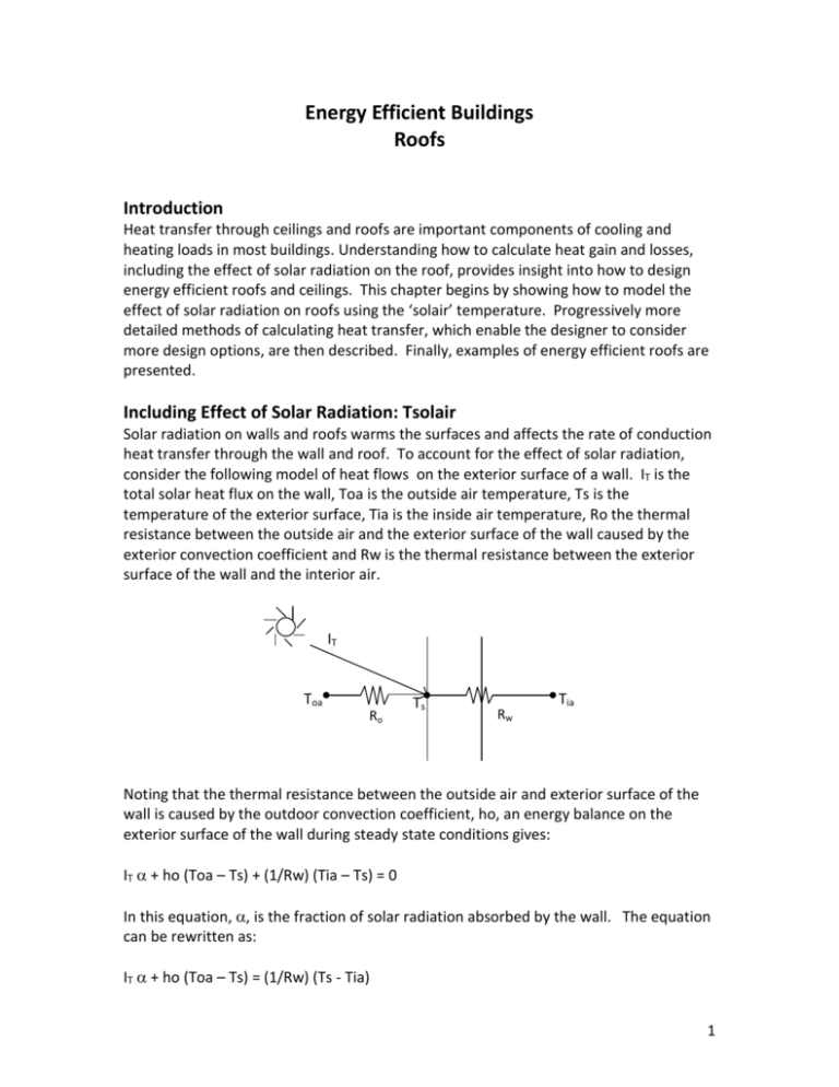
Energy Efficient Buildings Roofs Introduction Heat transfer through ceilings and roofs are important components of cooling and heating loads in most buildings. Understanding how to calculate heat gain and losses, including the effect of solar radiation on the roof, provides insight into how to design energy efficient roofs and ceilings. This chapter begins by showing how to model the effect of solar radiation on roofs using the ‘solair’ temperature. Progressively more detailed methods of calculating heat transfer, which enable the designer to consider more design options, are then described. Finally, examples of energy efficient roofs are presented. Including Effect of Solar Radiation: Tsolair Solar radiation on walls and roofs warms the surfaces and affects the rate of conduction heat transfer through the wall and roof. To account for the effect of solar radiation, consider the following model of heat flows on the exterior surface of a wall. IT is the total solar heat flux on the wall, Toa is the outside air temperature, Ts is the temperature of the exterior surface, Tia is the inside air temperature, Ro the thermal resistance between the outside air and the exterior surface of the wall caused by the exterior convection coefficient and Rw is the thermal resistance between the exterior surface of the wall and the interior air. IT Toa Ro Ts Rw Tia Noting that the thermal resistance between the outside air and exterior surface of the wall is caused by the outdoor convection coefficient, ho, an energy balance on the exterior surface of the wall during steady state conditions gives: IT + ho (Toa – Ts) + (1/Rw) (Tia – Ts) = 0 In this equation, , is the fraction of solar radiation absorbed by the wall. The equation can be rewritten as: IT + ho (Toa – Ts) = (1/Rw) (Ts - Tia) 1 The right side of this equation represents the heat transfer though the wall. The left side of the equation represents the energy gain of the surface of the wall from solar radiation and convection from the outside air. It is useful to reformulate the left side of the equation in terms of an effective outdoor air temperature, called solair temperature, Tsa, that includes the effect of the solar heat gain on the wall. Defining Tsa in this way, allows the left side of the equation to be expressed as: IT + ho (Toa – Ts) = (1/Rw) (Ts - Tia) ho (Tsa – Ts) = (1/Rw) (Ts - Tia) Setting the left sides of the two equations to be equal gives: IT + ho (Toa – Ts) = ho (Tsa – Ts) Solving for solair temperature, Tsa, gives: Tsa = Toa + (It / h) When Tsa is defined in this way, heat transfer through a wall or roof absorbing solar radiation can be calculated as: Qwall = (Awall / Rwall) (Tsa – Tia) = UAwall (Tsa – Tia) Example Calculate the heat transfer through a black, flat, R = 10 hr-ft2-F/Btu roof (including surface convection coefficients) with and without solar radiation if: Tia = 70°F Toa = 82 F absorbance of roof = 0.90 Ih = 244 Btu/hr-ft2 ft2-F Neglecting Solar Radiation Btu Q c Toa Tia 82 70 1 .2 2 Ac Rc 10 hr ft h = 4 Btu/hr- Including Solar Radiation Tsa Toa I 244 .90 82 137 F h 4 Btu Q c Tsa Tia 137 70 6.7 2 Ac Rc 10 hr ft In this example, neglecting the effect of solar radiation would underestimate heat transfer through the roof by more than 500%! 2 The effect of solar radiation on heat gain through building structures is greatest when IT is high, α is high and ho is low, Thus, it is especially critical to include the effect of solar radiation on flat, dark roofs during summer, when all three of these conditions are frequently present. Heat Loss Gain through Roofs with No Attic If a building has no attic, then the thermal resistance of the roof and ceiling can be combined, and heat gain/loss through a ceiling can be calculated using the same method as heat gain/loss through walls. Tsa Tsa Rc Tia Vaulted Ceiling / Roof Tia Flat Ceiling / Roof Q ceil UA ceil Tia Tsa Heat Gain and Loss through Roofs with Attics Many buildings have unconditioned attics with insulated ceilings. The heat gain through a ceiling depends on the attic ventilation rate, the solar radiation incident on sloping roofs, and on radiant heat transfer from the roof to the ceiling. Three methods for calculating heat gain/loss through the ceilings are presented below. Simplified Method Because of the difficulty of calculating the differential solar gain on multiple sides of a roof and because the natural attic ventilation rate is highly variable, the simplified method for approximating heat gain/loss through ceilings in buildings with attics is to: model the attic as an air space with R = 2 hr-ft2-F/Btu model the sloped roof as a flat roof with area equal to the ceiling 3 Example Consider a building with: Tia = 70°F Toa = 82 F absorbance of roof = 0.90 Ihorizontal = 244 Btu/hr-ft2 hext = 4 Btu/hr-ft2-F Rroof = 3 hr-ft2-F/Btu Rceil = 10 hr-ft2-F/Btu Aceil = 1500 ft2 where Rroof and Rceil include convection coefficients. Calculate the heat transfer through a sloped roof, attic and ceiling using the simplified method. Tsa = Toa + Ih / hext = 82 F + (244 Btu/hr-ft2 0.90) / 4 Btu/hr-ft2-F = 137 F Qc = [Aceil / (Rroof + Rattic + Rceil)] (Tsa – Tia) Qc = [1,500 ft2 / (3 + 2 + 10) hr-ft2-F/Btu] (137 – 70) F = 6,700 Btu/hr Attic Temperature Method Attic air temperature is affected by heat transfer through the roof, heat transfer through the ceiling, and the rate of ventilation air entering and leaving the attic. The figure below shows these major heat flows. In this model, heat loss/gain through the ceiling is driven by the difference between the indoor air temperature and attic temperature. Thus, the attic temperature must be calculated prior to calculating heat/loss gain through the ceiling. Gable vents Tsa Rr oo f R ven Ta Rceil t Toa Soffit vents Tia 4 To calculate attic temperature, Ta, write an energy balance on Ta. Qroof + Qinf + Qceil = 0 (SS) UA roof Tsa Ta UA vent Toa Ta UA ceil Tia Ta 0 Solve the energy balance to get: Ta UA roof Tsa UA vent Toa UA ceil Tia UA roof UA vent UA ceil where UA vent V ρc p After Ta is calculated, the heat gain through the ceiling into the building is: Qc = UAceil (Ta- Tia) As in the case of the simplified method, model the sloped roof as a flat roof with area equal to the ceiling. Example Consider the following building. Tia = 70°F Toa = 82 F absorbance of roof = 0.90 Ihorizontal = 244 Btu/hr-ft2 hext = 4 Btu/hr-ft2-F Rroof = 3 hr-ft2-F/Btu Rceil = 10 hr-ft2-F/Btu Aceil = 1,500 ft2 Vattic = 100 cfm pcp = 0.018 Btu/ft3-F where Rroof and Rceil include convection coefficients. Calculate the heat transfer through a sloped roof, attic and ceiling using the attic temperature method. Tsa = Toa + Ihorizontal / hext = 82 F + (244 Btu/hr-ft2 0.90) / 4 Btu/hr-ft2-F = 137 F UAroof = Aroof / Rroof = 1,500 ft2 / 3 hr-ft2-F/Btu = 500 Btu/hr-F UAvent = Vattic pcp = 100 cfm 60 min/hr 0.018 Btu/ft3-F = 108 Btu/hr-F UAceil = Aceiling / Rceil = 1,500 ft2 / 10 hr-ft2-F/Btu = 150 Btu/hr-F Ta = [UAroof Tsa + UAvent Toa + UAceil Tia] / [UAroof + UAvent + UAceil ] Ta = [500 Btu/hr-F 137 F + 108 Btu/hr-F 82 F + 150 Btu/hr-F 70 F] / [500 Btu/hr-F + 108 Btu/hr-F + 150 Btu/hr-F] Ta = 116 F Qc = UAceil (Ta – Tia) = 150 Btu/hr-F (116 – 70) F = 6,900 Btu/hr 5 Attic Temperature and Radiation Method In the summer heat gain through attics and ceilings into buildings can be significant. Three strategies to reduce heat gain through the ceiling during summer are light colored shingles, attic ventilation fans and low emissivity radiant barriers. The effectiveness of these strategies can be explored by developing a model of ceiling heat gain which explicitly considers: radiation heat transfer from the sun onto the exterior of the roof radiation heat transfer from the under side of the roof to the attic floor attic ventilation The figure below shows the major heat flows through a roof, into an attic, and into a room. Qs Tsa Toa 1 Rv Vc Rr p Roof T1 R1 Q12 1 h1 Ta 1 R2 h2 T2 Attic Ceiling Rc Tia The radiation heat transfer from surface 1 to 2, Q12, is a function of the StephanBoltzman constant, , emissivities of the surfaces, , areas of the surfaces, A, and the fraction of radiation leaving surface 1 that is incident on surface 2 (view factor), f12. Q12 = [ T14 - T24 ] / [ (1-1) / (1 A1) + 1 / (A1 f12) + (1-2) / (2 A2) ] A steady state model of these heat flows includes energy balances on the nodes representing the solar temperature Tsa, the attic air Ta, attic ceiling T1 and attic floor T2. E-bal on Tsa: Tsa: Tsa = Toa + Qs alpharoof / hext E-bal on 1: A1 / Rr (Tsa - T1) + -Q12 + A1 h1 (Ta - T1) = 0 6 E-bal on 2: A2 / Rc (Tia - T2) + Q12 + A2 h2 (Ta - T2) = 0 E-bal on attic air: A1 h1 (T1 - Ta) + A2 h2 (T2 - Ta) + Va pcp (Toa - Ta) = 0 After solving the system of equations, the heat gain into the attic Qc can be calculated as: Qc = A2 / Rc (T2 - Tia) Example Consider a base case with a dark roof (alpharoof = 0.90), non-reflective surfaces on the underside of the roof (1 = 0.8) and top of the ceiling (1 = 0.8), and limited natural air flow through the attic (Va = 50 cfm). Other input data are: "Input data" Qs = 1000 "Btu/hr-ft2" A1 = 100 "ft2" A2 = 100 "ft2" Tia = 72 "F" Toa = 92 "F" h1 = 1/.92 "Btu/hr-ft2-F" h2 = 1/.92 "Btu/hr-ft2-F" hext = 4 "Btu/hr-ft2-F" Rr = 2 "hr-ft2-F/Btu" Rc = 10 "hr-ft2-F/Btu" Stephan Boltzman = 0.1714*(10^(-8)) f12 = 1 "view factor" pcp = 0.018 "Btu/ft3-F" Solving the system of equations, gives the heat flux into the room for the base case Qc = 1,142 Btu/hr. Adding light-colored shingles (alpharoof = 0.4), a low-emissivity radiant barrier on the underside of the roof (1 = 0.2) and an attic ventilation fan (Va = 500 cfm) reduces the heat flux into the roof to Qc = 284 Btu/hr. Thus, these measures reduce ceiling heat gain by 75%. 7 Field Inspection of Roof/Ceiling Insulation An effective way to gauge roof and ceiling insulation is to compare snow cover on roofs with similar sun exposures. The following set of pictures compares several roofs the morning after a light snow. 8 Energy Efficient Roofs Based on these principles, many strategies can be employed to reduce heat transfer through roofs. Use Light Colored Roofs and Shingles to Reduce Cooling Loads Light colored roofs and shingles reflect more sunlight than dark roofs and shingles, and reduce heat transfer through roofs into buildings. In cooling dominated climates, this is clearly an advantage. For climates with both heating and cooling, this creates a tradeoff between reduced cooling energy use in the summer and increased heating energy use in the winter. The methods described in this chapter can be used to analyze this situation. White singles on a net-zero energy use house in Industrial facility roof with both white and dark gravel. Colorado. Photo: NREL. The following graph shows an analysis of a particular case in which a white roof substantially reduced heat flux in the summer months when the sun is high in the sky and shines directly on the flat roof, but had a much smaller affect during winter months when sun is low in the sky. 9 Use Radiant Barriers in Attics Radiation heat transfer from the underside of the roof to the upper surface of the ceil can be cost-effectively reduced by lining the surfaces with shiny low-emissivity material. Radiant barriers are frequently placed on underside of the roof rather than the top of the ceiling so that dust does not gather on the surface and reduce the efficacy of the radiant barrier. Source: ORNL Use High Levels of Ceiling Insulation U.S. Department of Energy recommended levels of insulation are shown below. 10 Zone Attic Cathedral Ceiling 1 2 3 4 5 6 7 8 R (hr-ft2-F/Btu) 30 to 49 30 to 60 30 to 60 38 to 60 38 to 60 49 to 60 49 to 60 49 to 60 R (hr-ft2-F/Btu) 22 to 38 22 to 38 22 to 38 30 to 38 30 to 60 30 to 60 30 to 60 30 to 60 Wall Cavity Insulated Sheathing R (hr-ft2-F/Btu) R (hr-ft2-F/Btu) 13 to 15 None 13 to 15 None 13 to 15 2.5 to 5 13 to 15 5 to 6 13 to 21 5 to 6 13 to 21 5 to 6 13 to 21 5 to 6 13 to 21 5 to 6 Floor R (hr-ft2-F/Btu) 13 19 to 25 25 25 to 30 25 to 30 25 to 30 25 to 30 25 to 30 Source: http://www.energysavers.gov/tips/insulation.cfm In colder climates, the recommended ceiling insulation is up to R = 60 hr-ft2-F/Btu. R=60 insulation requires about 18-inches of fiberglass or blown insulation. To accommodate this much insulation, builders use special roofing details such as those shown below that raise the roof to accommodate the insulation. 11 Photos: NREL Green Roofs Roofs can be covered with soil and vegetation to create a “green roof”. Thermodynamically, green roofs: have lower solar absorptivity than black roofs add thermal mass, which reduces peak cooling and heating loads allow evaporation from the vegetation, which cools the roof. In addition, green roofs store and evaporate rain water, which decreases peak flow through a city’s storm sewer system. Green roofs may also create a pleasant space for building occupants, especially in urban environments where garden and lawn space is limited. Because of the density of buildings in highly urban areas, lower roof-top temperatures contribute to a lower air temperature for the entire city. Roof of Chicago City Hall with 22,000 ft2 garden. Cross section of green roof. Source: FEMP. FEMP http://www1.eere.energy.gov/femp/pdfs/fta_green_roofs.pdf The impact of the additional thermal mass from a green roof on peak cooling and heating loads can be estimated using a simple single-node finite difference approach. Consider the following model of a green roof. For simplicity, the only thermal mass considered is the thermal mass of the soil. 12 Tsa Rs Ts Rsr Soil Roof Tia Tsa is the solair temperature Ts is the temperature of the soil in the green roof Tia is the inside air temperature Rs is the thermal resistance of the soil above Ts, the middle of the soil. Rsr is the thermal resistance of the soil below Ts plus the thermal resistance of the roof. A is the area of the roof An energy balance on Ts gives: (A/Rs)(Tsa – Ts) + (A/Rsr)(Tia – Ts) = m cp (Ts+ - Ts) / dt Where: m is the mass of the soil cp is the specific heat of the soil Ts+ is the temperature of the soil at the end of time interval dt Ts is the temperature of the soil at the beginning of time interval dt Noting that m = A dx where dx is soil thickness and is soil density, the energy balance equation can be solved for Ts+ to give: Ts+ = Ts + dt /(dx r cp) [ (Tsa – Ts)/Rs + (Tia – Ts)/Rsr ] In an hour-by-hour finite difference simulation, the initial value of Ts would guessed and subsequent values of Ts+ would be calculated using Ts from the previous hour. After Ts is known, the transient heat transfer into the building, Q, which includes the thermal energy storage of the green roof, is: Q = (A/Rsr) (Ts – Tia) The steady state heat transfer into the building, Qss, which ignores the thermal energy storage of the green roof, is simply: Qss = A/(Rs + Rsr) (Tsa – Tia) 13 Example Calculate the hourly steady-state and transient heat fluxes (Btu/hr-ft2) into a building through a 6”inch green roof on top of a R = 10 traditional roof. Assume the solair temperature varies sinusoidally over a 24-hour period about a mean temperature of 80 F with an amplitude of 10 F. Soil properties are: dx = 0.5 ft = 109 lb/ft3 cp = 0.191 Btu/lb-F Rsoil = 1.846 hr-ft2-F/Btu per ft Thus: Rs = Rsoil x dx / 2 = 1.846 hr-ft2-F/Btu per ft x 0.25 ft = 0.462 hr-ft2-F/Btu Rsr = Rroof + Rsr = (10 + 0.462) hr-ft2-F/Btu = 10.462 hr-ft2-F/Btu Hourly values of Tsa over a 24 hour period are calculated as: Tsa = Tsa,mean + Tsa,amp x Sin (2 pi hr / 24) For hr = 1, Ts is set to 70 F as an initial condition. In all subsequent hours, Ts+, which is soil temperature at the end of the hour, is calculated from: Ts+ = Ts + dt /(dx cp) [ (Tsa – Ts)/Rs + (Tia – Ts)/Rsr ] After Ts is known, the transient and steady state heat fluxes into the building are calculated as: Q = (A/Rsr) (Ts – Tia) Qss = A/(Rs + Rsr) (Tsa – Tia) The simulation is run for four 24-hour periods to remove the effects of the initial condition. The graph below shows that after the effects of the initial conditions become negligible, peak soil temperature is about 4 F less that peak solair temperature and lags behind peak solair temperature by about 3 hours. Thus, the temperature driving heat into the building is both reduced and lagged by the thermal mass of the soil. 14 The graph below shows that after the effects of the initial conditions become negligible, peak heat flux into the building is reduced from 1.83 to 1.54 Btu/hr-ft2, a reduction of about 16%. In addition, the peak heat flux has been delayed by about 3 hours. This delay may shift the peak into hours during which the building is unoccupied. This combination could result in lower electrical demand charges and reduce the required capacity and cost of the cooling system. In addition, peak cooling may now occur when the outside air temperature is cooler. This would enable the cooling equipment to operate at a higher efficiency. 15


