RPI_HW_fnd_2_
advertisement
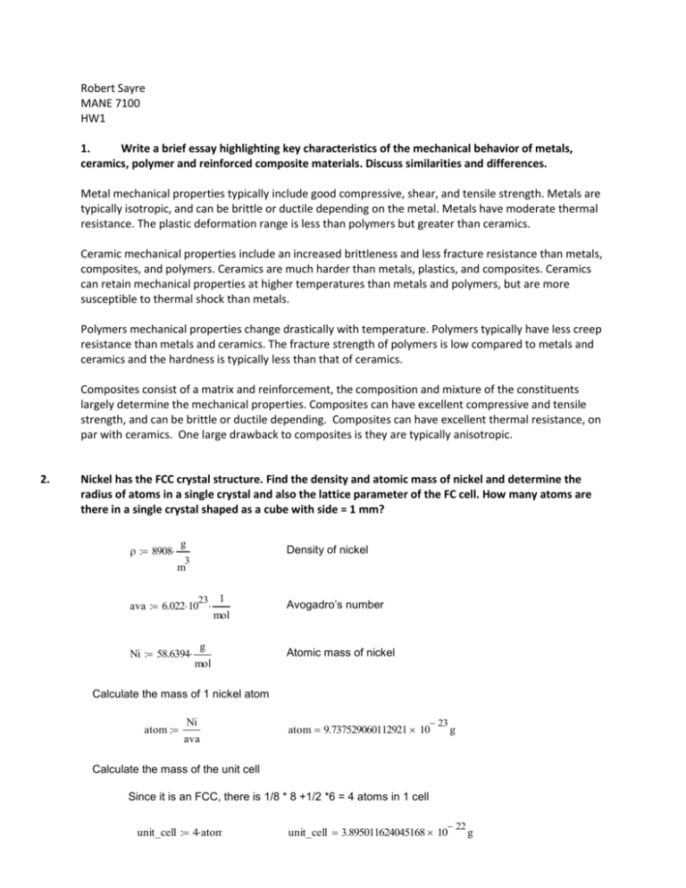
Robert Sayre MANE 7100 HW1 1. Write a brief essay highlighting key characteristics of the mechanical behavior of metals, ceramics, polymer and reinforced composite materials. Discuss similarities and differences. Metal mechanical properties typically include good compressive, shear, and tensile strength. Metals are typically isotropic, and can be brittle or ductile depending on the metal. Metals have moderate thermal resistance. The plastic deformation range is less than polymers but greater than ceramics. Ceramic mechanical properties include an increased brittleness and less fracture resistance than metals, composites, and polymers. Ceramics are much harder than metals, plastics, and composites. Ceramics can retain mechanical properties at higher temperatures than metals and polymers, but are more susceptible to thermal shock than metals. Polymers mechanical properties change drastically with temperature. Polymers typically have less creep resistance than metals and ceramics. The fracture strength of polymers is low compared to metals and ceramics and the hardness is typically less than that of ceramics. Composites consist of a matrix and reinforcement, the composition and mixture of the constituents largely determine the mechanical properties. Composites can have excellent compressive and tensile strength, and can be brittle or ductile depending. Composites can have excellent thermal resistance, on par with ceramics. One large drawback to composites is they are typically anisotropic. 2. Nickel has the FCC crystal structure. Find the density and atomic mass of nickel and determine the radius of atoms in a single crystal and also the lattice parameter of the FC cell. How many atoms are there in a single crystal shaped as a cube with side = 1 mm? g 8908 Density of nickel 3 m 23 ava 6.022 10 Ni 58.6394 1 Avogadro’s number mol g Atomic mass of nickel mol Calculate the mass of 1 nickel atom atom Ni ava 23 atom 9.737529060112921 10 g Calculate the mass of the unit cell Since it is an FCC, there is 1/8 * 8 +1/2 *6 = 4 atoms in 1 cell unit_cell 4 atom 22 unit_cell 3.895011624045168 10 g Calculate the volume using the unit cell mass and density unit_cell vol 3 vol 43.724872295073716 nm 17 vol 4.372487229507372 10 3 mm Calculate the side length from the volume Since it is a cube the volume is equal to side cubed 1 side ( vol) 9 3 side 3.523 10 m side 3.523 nm Calculate the radius r 9 side r 1.246 10 2 2 m r 1.246 nm len 1 mm Length of side of new cube Calculate how many atoms fit in 1 length of a cube num len 5 num 4.014 10 2 r Calculate how many atoms total in the cube 6 3 num 1.204 10 atoms 3. The fraction of vacant lattice sites Nv , in an otherwise perfect crystal of Pt is given as a function of the absolute temperature T (in Kelvin) by the expression where the Boltzmann constant k =1:38 10 – 23 J=moleK. Calculate and plot the value of Nv for the temperature range 300 <= T <= 2042. 23 k 1.38 10 boltzman constant temp 300301 2042 Temperature range 2.56 10 19 kT Nv ( T) e 1.510 110 Fraction of vacant lattice sites 4 4 Nv( temp ) J mol 510 5 0 0 500 110 3 temp K 1.510 3 210 3 4. The density of dislocations in heavily worked nickel is of the order of 1016 dislocation lines per square meter. Assume that the dislocations are randomly arranged and estimate the average space between neighboring dislocation lines. 16 1 dis 10 2 m Dislocation density assume the dislocations are all edge type Need to find the average length, in a square the dislocation density dictates the average distance between dislocations per length of the side of a square. The number of dislocations per side squared (since it is a square) = the area of the dislocation area. side 5. 8 1 side 1 10 m dis Review your basic knowledge of strength of materials and then consider a simply supported beam of length L , elastic modulus E and moment of inertia I : a.-Obtain an expression for the maximum deflection of the beam due to the application of a point load P downwards, applied in the middle of the upper surface of the beam. Deflection = moment/ flexural modulus 2 M d E I dx 2 y Differentiating once yields: 3 V d E I dx 3 Where V is the first derivative y Differentiating twice yields: 4 q d E I dx 4 y Where q is the loading Integrating once yields: E I d y dx Where θ is the slope Integrating twice yields: y f ( x) The integral forms of these equations in the bounds 0<x<l: V M q d x C1 V d x C1 x C2 y 3 2 d x C1 x C2 x C3 x C4 M 2 d x C1 x C2 x C3 E I Summing the moments about the right hand side and summing the forces in the y direction. Mz R1 L 0 P ( L x) 2 2 i R1 w ( L x) 2 2 L Fy 0 R1 w ( L x) R2 i R2 w ( L x) 2 w ( L x) 2 L loading function: q R1 ( x 0) 1 0 P ( x L) R2 ( x l) 1 Integrating: V q dx M Vdx M dx y dx Find the four constants of integration: Since the reaction force and moments are included in the loading function C.1 and C.2 are zero C1 0 C2 0 Since the deflection is zero at the supports, The BC's are as follows: y( 0) 0 y( L) 0 Then C4 C3 0 P ( L x) 2 L ( L x) 4 24 L 2 2 The resulting deflection is then: y P 2 ( l x) x ( L x) 2 L ( L x) x L ( x x) 2 24 L E I 3 4 2 2 4 Max deflection occurs at the point where the slope curve is zero: R1 1 E I 2 P 2 x 6 x C3 2 L 3 0 Plugging the value of x into the deflection eqn and simplifying yields: 3 y max_point P L E I b.-Obtain an expression for the maximum deflection of the beam due to the application of a distributed load per unit length Q , downwards, applied on the upper surface of the beam. Deflection = moment/ flexural modulus 2 M d E I dx 2 y Differentiating once yields: 3 V d E I dx 3 y Where V is the first derivative Differentiating twice yields: 4 q d E I dx 4 y Where q is the loading Integrating once yields: E I d y dx Where θ is the slope Integrating twice yields: y f ( x) The integral forms of these equations in the bounds 0<x<l: V M q d x C1 V d x C1 x C2 y 3 2 d x C1 x C2 x C3 x C4 M E I 2 d x C1 x C2 x C3 Summing the moments about the right hand side and summing the forces in the y direction. Mz R1 L 0 w ( L a) 2 2 i R1 w ( L a) 2 2 L Fy 0 R1 w ( L a) R2 i R2 w ( L a) 2 w ( L a) 2 L loading function: q R1 ( x 0) 1 0 w ( x a) R2 ( x l) 1 Integrating: V q dx M Vdx M dx y dx Find the four constants of integration: Since the reaction force and moments are included in the loading function C.1 and C.2 are zero C1 0 C2 0 Since the deflection is zero at the supports, The BC's are as follows: y( 0) 0 y( L) 0 Then C4 C3 0 w 24 L ( L a) 2 L ( L a) 4 2 2 The resulting deflection is then: y w 24 L E I 2 ( l a) x ( L a) 2 L ( L a) x L ( x a) 2 3 4 2 2 4 Max deflection occurs at the point where the slope curve is zero: R1 2 w 3 x ( x a) C3 E I 2 6 1 0 Plugging the value of x into the deflection eqn and simplifying yields: y max_uni 5 3 w L 384 E I c.- Consider a beam of square cross section a = b =0:1 m, moreover let L =1m and E =10 11Pa. Calculate the values of the maximum beam deflection for cases (a) and (b) above if P =105N and Q =105N/m, respectively. a 0.1 m Beam cross section b 0.1m L 1 m Length 11 E 10 Pa Modulus of elasticity 5 N W 10 Uniform loading m 5 P 10 N Point load Moment of inertia I a b 3 6 4 I 8.333 10 12 m Part A: Point Load 3 y max_point P L ymax_point 0.12m E I Part B: uniform load Equivalent load w W L 5 w 1 10 N y max_uni 5 3 w L 384 E I 3 ymax_uni 1.562 10 m 6. The state of stress at a point in a structural component is specified by the following components of the stress tensor (all in MPa): a.- Compute the values of the first three stress invariants of the stress tensor. known 11 0 22 200 33 280 12 240 13 2.4 23 0 21 12 31 13 32 23 11 12 13 matrix 21 22 23 31 32 33 Kroenecker delta 1 0 0 ij 0 1 0 0 0 1 Three stress invariants I1 11 22 33 I2 22 23 11 13 11 12 32 33 31 33 21 22 I3 matrix I1 80 5 I2 1.136 10 7 I3 1.613 10 b.- Solve the characteristic equation of the stress tensor and determine the values of the principal stresses. 2.4 240 matrix ij 240 200 0 0 280 2.4 Characteristic eqn chareqn matrix ij 2 3 chareqn 113605.76 80.0 1.0 1.6126848e7 guess 0 given 113605.76 80.0 1.0 1.6126848e7 2 z find ( ) 280.03598988084296144 z 159.96677937112552594 360.00276925196848739 T 280.03598988084296144 ztrans 159.96677937112552594 360.00276925196848739 Principal Stresses 1 360.003 3 280.036 1 max ztrans 3 min ztrans 2 I1 1 3 2 159.967 3 0 c.- Compute the hydrostatic stress and the components of the stress deviator tensor Hydrostatic stress tensor: Calculate the mean stress: p I1 3 p 26.667 Then the hydrostatic stress tensor is: 0 0 26.667 hydro 0 26.667 0 0 26.667 0 hydro p ij The stress deviator tensor is: 2.4 26.667 240 deviator 240 226.667 0 0 253.333 2.4 deviator matrix hydro d.- Compute the values of the first three invariants of the stress deviator tensor. J1 0 1 2 J2 I1 I2 3 J2 4 10 J3 deviator J3 1.306 10 4 7 e.- Solve the characteristic equation of the stress deviator tensor and determine the values of the principal stress deviations and give the values of the principal shearing stresses. Characteristic eqn chareqn2 deviator 1 ij 3 chareqn2 115739.09333333333333 1 1.0 1 1.3059435140740740741e7 solve block guess 1 0 3 115739.09333333333333 1 1.0 1 1.3059435140740740741e7 Given 0 z1 Find 1 transpose the answer 133.30011270445885928 z1 386.66943591863515405 253.36932321417629477 T 133.30011270445885928 ztrans_1 386.66943591863515405 253.36932321417629477 Principal Deviator Stresses s 1 max ztrans_1 s 1 386.669 s 3 min ztrans_1 s 3 253.369 s 2 J1 s 1 s 3 s 2 133.3 Since s kk 0 then the stress deviator tensor is in a state of pure shear, and the principle shear stresses are the same as the stress deviator tensor principle stresses.
