Activity 9 Mechanics of Materials Name: ID: For the figure shown

Activity 9 Mechanics of Materials
Name: _________________________________________________________ ID: ________________
1.
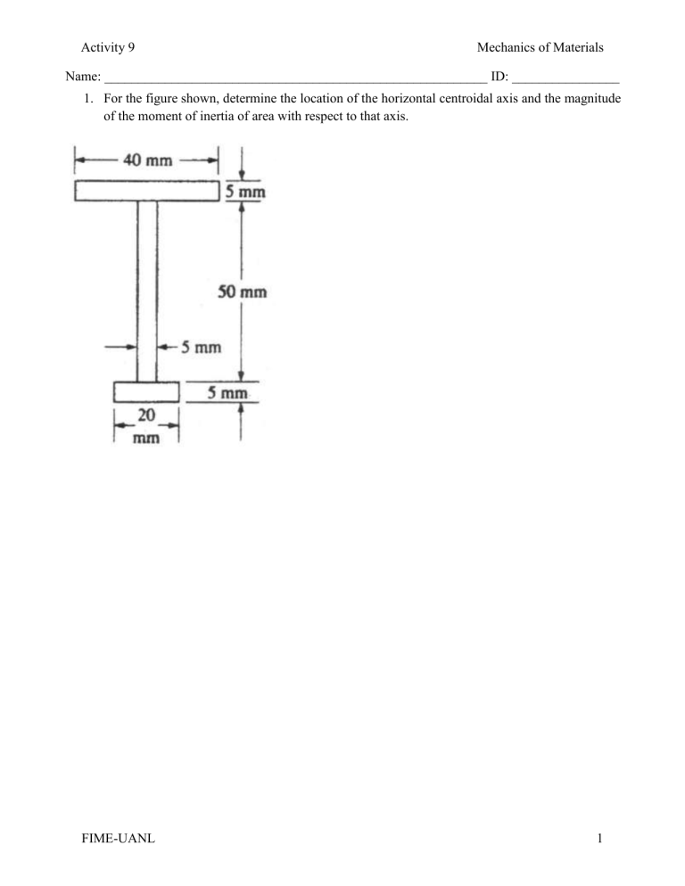
For the figure shown, determine the location of the horizontal centroidal axis and the magnitude of the moment of inertia of area with respect to that axis.
FIME-UANL 1
Activity 9 Mechanics of Materials
Name: _________________________________________________________ ID: ________________
2.
Determine the position for the centroid, then find the moment of inertia of area and for the C shaded area.
FIME-UANL 2
Activity 9 Mechanics of Materials
Name: _________________________________________________________ ID: ________________
3.
Determine the position for the centroid, then find the moment of inertia of area Ix and Iy for the T shape.
FIME-UANL 3
Activity 9 Mechanics of Materials
Name: _________________________________________________________ ID: ________________
4.
Determine the Y position for the centroid, then find the moment of inertia of area Ix and Iy for the
U shape.
FIME-UANL 4
Activity 9 Mechanics of Materials
Name: _________________________________________________________ ID: ________________
5.
Determine the moment of inertia of area with respect to the symmetry axes of the composed section, in the figure, formed by two plates of 400 mm x 20 mm joined with two profiles C310 x 31.
FIME-UANL 5
Activity 9 Mechanics of Materials
Name: _________________________________________________________ ID: ________________
6.
Determine the maximum moment of flexion in the girder.
FIME-UANL 6
Activity 9 Mechanics of Materials
Name: _________________________________________________________ ID: ________________
7.
Determine the maximum moment of flexion in the girder.
FIME-UANL 7
Activity 9 Mechanics of Materials
Name: _________________________________________________________ ID: ________________
8.
Determine the maximum moment of flexion in the beam.
FIME-UANL 8
Activity 9 Mechanics of Materials
Name: _________________________________________________________ ID: ________________
9.
Determine the maximum moment of flexion in the beam.
FIME-UANL 9
Activity 9 Mechanics of Materials
Name: _________________________________________________________ ID: ________________
10.
Determine the maximum moment of flexion in the girder.
FIME-UANL 10
Activity 9 Mechanics of Materials
Name: _________________________________________________________ ID: ________________
11.
Determine the minimum width b of the beam in the figure, so the maximum normal stress does not exceed 10MPa.
FIME-UANL 11
Activity 9 Mechanics of Materials
Name: _________________________________________________________ ID: ________________
12.
For the beam and load shown in the figure, design the cross section knowing that the permissible normal stress in the wood is 12MPa.
FIME-UANL 12
Activity 9 Mechanics of Materials
Name: _________________________________________________________ ID: ________________
13.
The steel shaft has a circular cross section with 2in of diameter. Is supported with rolling bears at A and B. Determine the maximum stress of flexion in the shaft when is supporting the loads showed in the pulleys.
FIME-UANL 13
Activity 9 Mechanics of Materials
Name: _________________________________________________________ ID: ________________
14.
The T beam is supported and loaded as shown in the figure. The cross section is detailed; determine the maximum stresses of tension and compression in the beam.
FIME-UANL 14
Activity 9 Mechanics of Materials
Name: _________________________________________________________ ID: ________________
15.
The simply supported thin I profile has the loads and cross sectional dimensions showed in the figure. Calculate the maximum stress of tension.
FIME-UANL 15


