Section 17 ITS - Minnesota Department of Transportation
advertisement
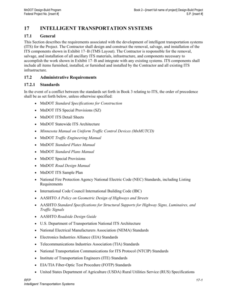
MnDOT Design-Build Program Federal Project No. [insert #] Book 2—[insert full name of project] Design-Build Project S.P. [insert #] 17 INTELLIGENT TRANSPORTATION SYSTEMS 17.1 General This Section describes the requirements associated with the development of intelligent transportation systems (ITS) for the Project. The Contractor shall design and construct the removal, salvage, and installation of the ITS components shown in Exhibit 17–B (TMS Layout). The Contractor is responsible for the removal, salvage, and installation of all ancillary ITS materials, infrastructure, and components necessary to accomplish the work shown in Exhibit 17–B and integrate with any existing systems. ITS components shall include all items furnished, installed, or furnished and installed by the Contractor and all existing ITS infrastructure. 17.2 Administrative Requirements 17.2.1 Standards In the event of a conflict between the standards set forth in Book 3 relating to ITS, the order of precedence shall be as set forth below, unless otherwise specified: MnDOT Standard Specifications for Construction MnDOT ITS Special Provisions (SZ) MnDOT ITS Detail Sheets MnDOT Statewide ITS Architecture Minnesota Manual on Uniform Traffic Control Devices (MnMUTCD) MnDOT Traffic Engineering Manual MnDOT Standard Plates Manual MnDOT Standard Plans Manual MnDOT Special Provisions MnDOT Road Design Manual MnDOT ITS Sample Plan National Fire Protection Agency National Electric Code (NEC) Standards, including Listing Requirements International Code Council International Building Code (IBC) AASHTO A Policy on Geometric Design of Highways and Streets AASHTO Standard Specifications for Structural Supports for Highway Signs, Luminaires, and Traffic Signals AASHTO Roadside Design Guide U.S. Department of Transportation National ITS Architecture National Electrical Manufacturers Association (NEMA) Standards Electronics Industries Alliance (EIA) Standards Telecommunications Industries Association (TIA) Standards National Transportation Communications for ITS Protocol (NTCIP) Standards Institute of Transportation Engineers (ITE) Standards EIA/TIA Fiber-Optic Test Procedure (FOTP) Standards United States Department of Agriculture (USDA) Rural Utilities Service (RUS) Specifications RFP Intelligent Transportation Systems 17-1 MnDOT Design-Build Program Federal Project No. [insert #] Book 2—[insert full name of project] Design-Build Project S.P. [insert #] Remaining standards set forth in Book 3 17.2.2 Meetings Work with MnDOT to form an ITS design team to oversee and provide input on the ITS design and construction. 17.2.2.1 ITS Design Workshop Schedule an ITS design workshop prior to initiation of design plans or any work that disrupts existing ITS infrastructure. The ITS design workshop shall include the MnDOT Project Manager and MnDOT ITS staff. Coordinate with MnDOT to determine if additional stakeholders such as FHWA, affected cities and counties, or others should be invited to participate in the workshop. The ITS design workshop is intended to build consensus on the goals, parameters, and overall functionality and feasibility of the system. At the ITS design workshop, present draft ITS Conceptual Plan, with hardcopy layouts, including the following topic areas: Salvaged, installed, or removed ITS infrastructure CCTV surveillance at signals system Fiber-optic cable/conduit location Blown-in fiber (practices and procedure) Vault locations Connection to in-place ITS infrastructure Cabinet and shelter locations Fiber-optic cable splicing and testing Locating ITS components (DMS, cameras) State-provided equipment lead-time Worker certifications Component testing Test equipment calibration ITS construction best practices Documentation, GPS coordinates, as-built, and submittal requirements Temporary ITS infrastructure including o Contractor’s plan for construction staging specific to the ITS infrastructure including the plan for maintaining communication to devices and the length of down time for unavailable devices. 17.2.2.2 ITS Design Progress Meetings During the ITS design development, organize, schedule, and conduct every-other-week meetings with the ITS design team and affected cities and counties to discuss progress of the ITS design. Hold design progress meetings until As-Built Documents have been submitted. Take meeting minutes and distribute them within on Working Day via email to the ITS design team, meeting attendees and MnDOT. To monitor design progress and assist in the conduct of these meetings, provide location maps for review and inspection which show all proposed locations for ITS components and how the equipment locations interrelate to form the ITS component system. Schedule, organize, and conduct the ITS design progress meetings to accomplish the following: RFP Intelligent Transportation Systems 17-2 MnDOT Design-Build Program Federal Project No. [insert #] Book 2—[insert full name of project] Design-Build Project S.P. [insert #] Review existing ITS systems and operations, including field verification of all legacy ITS systems and components Define and finalize ITS functional, technical, operational, and maintenance requirements Finalize goals and parameters of ITS design Establish integration requirements Develop Acceptance of ITS design Address and discuss ITS construction issues 17.2.2.3 FO System Test Plan Meeting Prior to any FO cable installation, arrange a meeting with MnDOT to discuss the proposed Fiber-Optic (FO) System Test Plan. Testing personnel, including field testing personnel, shall attend the meeting. The meeting may be waived if the Testing personnel have historically demonstrated their ability to conform to MnDOT FO Cable Testing requirements. 17.2.3 Equipment/Software 17.2.4 Permits/Authorizations 17.3 Design Requirements 17.3.1 General Requirements Provide complete, operational, and maintainable ITS and ITS components. Design the ITS Components by placing them in a location that generally conforms to the locations shown in Exhibit 17–B while allowing flexibility to move the ITS Components to meet the specific requirements of Book 3 and other Contract requirements. ITS Components can move up to 25’ from the locations shown in Exhibit 17-B without MnDOT Approval. Ensure these systems and components are compatible with the in-place legacy system and any MnDOT planned future system. Label the ITS devices with MnDOT-provided naming and numbering convention. Provide an ITS design that includes the following devices and equipment [list item(s) and provide a general location of where they should be placed] 17.3.1.1 Has Met and Approved Products List (APL) The term “Has Met” refers to a Manufacturer’s product that is in conformance with the applicable specifications. Submit any other Manufacturer’s product of equal quality or better to MnDOT for Approval. The term “APL” refers to the MnDOT-Approved Products List. These products are in conformance with the applicable specifications. Submit other manufacturer’s products of equal quality by following the guidelines for acquiring approval to list a product on the APL. See the following website for MnDOT Approved Product List (APL): http://www.dot.state.mn.us/products/trafficmgtsystems/index.html 17.3.2 Investigations/Supplemental Work 17.3.3 Design Criteria 17.3.3.1 Communication Network Perform the following: Maintain the existing communications functionality during construction. Design and construct a communications network to serve the ITS components along the segments of the Project. RFP Intelligent Transportation Systems 17-3 MnDOT Design-Build Program Federal Project No. [insert #] Book 2—[insert full name of project] Design-Build Project S.P. [insert #] Provide communication links with proposed ITS components to in-place components that are not located within the right of way or within the project limits. Do not substitute or apply any part or attach any piece of equipment contrary to the manufacturer’s recommendations and standard practices. 17.3.3.1.1 Fiber-Optic Cable Perform the following: Locate fiber-optic trunk cable that runs parallel to overhead electrical transmission lines as far from the transmission lines as possible to minimize induced voltage onto the FO armored jacket. Furnish and install new fiber-optic cable in the general locations shown in Exhibit 17–B. Minimize the number of transverse crossings of the freeway. Place all permanent FO cables within conduit. Provide armored FO pigtails between splice vaults/shelter and field device control cabinets. Provide a minimum size FO trunk cable of 72 SM. Provide the necessary pigtails to control cabinets and terminate the FO pigtail with the specified connectors. It is not required to upgrade the existing hub communications end equipment. Provide and install the necessary fiber termination equipment (i.e., fiber distribution frame, fiber splice modules, fiber patching modules) to accommodate the increased number of fibers in the trunk fiber-optic cable line. Fiber-optic cable for devices outside the Project limits routed through the Project limits will be rerouted by MnDOT. See APL website for approved products list. Do not use wireless communications for the ITS communications network. 17.3.3.1.2 Fiber-Optic Cable Assemblies Furnish and install FO cable assemblies as required by the ITS design for this project. Assemble the fiberoptic cable as described in the USDA RUS 7 CFR 1755.900 specification and comply with the specifications required by the Manufacturers of approved MnDOT part numbers contained within this document or found on the MnDOT APL. See APL website for approved products list. No Factory Fusion splices shall be allowed on FO cable. 17.3.3.1.3 Fiber-Optic Connection Components Indoor Pigtails—Furnish and install indoor pigtails. 17.3.3.1.4 Coaxial Cables Do not use coaxial cable other than when it is provided by MnDOT. 17.3.3.2 Closed Circuit Television (CCTV) System Furnish and install new CCTV hardware at the locations indicated on Exhibit 17–B. Consult with MnDOT on the placement of CCTV. Because camera views, accessibility, and maintainability are issues of concern, obtain input from MnDOT. CCTV systems within the Project Limits are to remain operational during construction. Provide a CCTV system that meets the following requirements: CCTV pole-mounted control cabinet Sidewalks adjacent to the CCTV standard Cabling Maximum 1-mile spacing Overlapping coverage RFP Intelligent Transportation Systems 17-4 MnDOT Design-Build Program Federal Project No. [insert #] Book 2—[insert full name of project] Design-Build Project S.P. [insert #] Coverage to remotely monitor highway or connecting arterial street traffic conditions and, if possible, confirm messages displayed on any remotely controlled dynamic message sign (DMS) Placement to allow monitoring of ramp metering and ramp queues, if applicable Maintenance-free, to the extent possible Lightning and surge protection Do not place standards and cameras in the median of the highway. In the Twin Cities metro area, ensure the CCTV system is compatible with the current video switch (Pelco). 17.3.3.2.1 CCTV Hardware—Folding Pole Design the pole to meet the following requirements: [list item(s)] See APL website for approved products list. 17.3.3.2.2 CCTV Hardware Cables MnDOT will provide the CCTV hardware cables. 17.3.3.2.3 CCTV Pole Mounted Control Cabinet Provide and install the CCTV pole-mounted control cabinet. See APL website for approved products list. 17.3.3.3 Dynamic Message Signs (DMS) MnDOT will furnish the DMS for installation by the Contractor. Furnish and install the DMS support structure. See Signing sections for additional details. Design the DMS support structure using a Structural Engineer licensed in the State of Minnesota. Provide a walkway on the DMS structure that extends over the roadway to the outside edge of the shoulder or to the edge of the structure as approved by MnDOT. Mount the DMS to the support structure positioning the signs to allow motorists to select alternate routes and to advise travelers of adverse road conditions, including construction-related congestion. Minnesota State Patrol personnel and MnDOT personnel will change the messages on the signs. Place DMS signs in the approximate locations as indicated in Exhibit 17–B unless otherwise Approved by MnDOT. DMS signs can be moved within 50’ of the location identified in Exhibit 17–B without the need for additional geotechnical information for foundation design to be obtained and paid for by the Contractor. Locate the DMS so no lane closures are required to perform maintenance. Install a paved parking pad and roadside hazard protection for maintenance vehicle access at all DMS locations. Size the paved parking pad to accommodate an aerial lift truck and a standard pick-up truck with both vehicles located simultaneously on the paved parking pad. 17.3.3.4 TMS Shelter Cabinet Furnish and install a TMS shelter cabinet with a climate-controlled environment for electric, electronic, and FO devices. 17.3.3.4.1 Electrical Conduit Provide galvanized steel or corrosion resistant metal conduit raceways, fittings, and hardware. 17.3.3.4.2 Electrical Wiring Provide copper wire only. 17.3.3.4.3 Lighting Provide minimum illumination at floor level of 150 fe. RFP Intelligent Transportation Systems 17-5 MnDOT Design-Build Program Federal Project No. [insert #] 17.3.3.4.4 Book 2—[insert full name of project] Design-Build Project S.P. [insert #] Duplex Receptacles Provide receptacles of 20 amps and 110 volts. 17.3.3.4.5 Cable Tray Provide cable trays that meet the following: 254 mm (12 inches) wide 3.05 m (12 feet) long 17.3.3.5 Control Cabinets Control cabinets will be furnished by MnDOT. 17.3.3.6 Handholes Furnish and install handholes in accordance with MnDOT Standard Specification 2565.3. Modify proposed handholes to accommodate existing conduit as needed. 17.3.3.7 FO Splice Vault and Pull Vault 17.3.3.7.1 FO Splice Vault Provide FO splice vault. See APL website for approved products list. 17.3.3.7.2 Pull Vault Provide pull vault. See APL website for approved products list. 17.3.3.8 NMC Conduit and Bored Conduit Furnish and install conduit systems for power and communication systems that comply with the NEC and the local standards. Do not use buried rigid steel conduit (RSC) except under rail crossings as negotiated with railroad companies and under or within bridges. 17.3.3.8.1 Existing Conduit Systems Existing conduit systems may consist of stick PVC, stick polyethylene, continuous polyethylene, or RSC. 17.3.3.8.2 Air-assisted Cable Installation 17.3.3.8.3 Bored Conduit Use Bored Conduit with the following requirements except as modified by these specifications: NMC complies with MnDOT 3803 RSC complies with MnDOT 3801 Expansion fittings utilized, as needed, in compliance with MnDOT 3839 17.3.3.9 Electrical Service Do not share electrical service for ITS components with other roadway components. 17.3.3.9.1 Coordination with Power Utility Perform the following: Process an application for electrical service for each location Coordinate with the Utility to ensure the proper location of electrical services provided by the Utility Provide the Utility company with the construction schedule so that power is available when needed RFP Intelligent Transportation Systems 17-6 MnDOT Design-Build Program Federal Project No. [insert #] 17.3.3.9.2 Book 2—[insert full name of project] Design-Build Project S.P. [insert #] Service Cabinet or Service Cabinet Type Special See APL website for approved products list. 17.3.4 Reports/Plans 17.3.4.1 ITS Conceptual Plan Submit the ITS Conceptual Plan to MnDOT for Acceptance prior to submitting any ITS RFC documents. At a minimum, denote the location of ITS components, construction, and testing schematics. 17.3.4.2 Maintenance and Operations Manual Supply as part of the Work all manufacturers’ maintenance and operations manuals for all equipment installed as part of the project. 17.3.4.3 Project Testing and Documentation Present Project Testing and Documentation Submittals directly to MnDOT as a complete package unless prior authorization is made with MnDOT. A complete package shall be defined as one assembled submittal for components and one assembled submittal for testing, which shall include all required documentation. Project Testing and Documentation Submittals are required for the following items: ITS Components Testing of FO cable 17.3.4.4 Fiber Optic Testing Documentation Use the “Fiber Optic Schematic” sheets in Exhibit 17–C as a guide for developing fiber optic schematics to record power meter and OTDR test data as well as the physical characteristics of the FO cable and FO cable run. See this Section 17 for FO Cable Test parameters and additional FO Cable testing information. 17.4 Construction Requirements Design the ITS system as a whole before installing any individual field component unless otherwise Approved by MnDOT. Notify MnDOT three Working Days in advance of staking locations for ITS components. Do not make final connections of the newly installed components to the existing system. 17.4.1 General Requirements Provide MnDOT a three-month advance notice of installation of CCTV hardware, cabinets, and equipment shelters. This lead-time is necessary to order communications end equipment. 17.4.1.1 Allowable Working Hours on the ITS System Do not affect ITS devices outside the Project limits; all must remain operable during construction of the Project. Ensure the Traffic Management System is fully operational Monday through Friday from 5:00 am to 9:00 am and 3:00 pm to 7:00 pm unless approved by MnDOT. Notify MnDOT prior to taking down active system elements. Perform all work in a manner ensuring the integrity and proper performance of all ITS components during these hours. Contact MnDOT 48 hours prior to performing any work on existing/active ITS devices. 17.4.1.2 Maintenance/Operation of ITS Components Maintenance and operation includes the Contractor’s response to faults. There are three categories of faults: urgent, priority, and minor, as follows: Urgent—Any fault that causes a total failure, disruption, or system-wide disruption of the following equipment or services: Communications links and equipment RFP Intelligent Transportation Systems 17-7 MnDOT Design-Build Program Federal Project No. [insert #] Book 2—[insert full name of project] Design-Build Project S.P. [insert #] CCTV The response time for urgent faults of ITS components shall be less than four hours. The repair time for urgent faults of ITS components shall be less than four hours after the response. Priority—Any fault that causes a failure or disruption of an operator workstation, local control unit for DMS, or the DMS itself. The response time shall be by noon the next day. The repair time shall be less than four hours. Minor—Any other fault. The response time shall be by midnight of the next day. The repair time shall be less than four hours. Replace (do not repair) ITS infrastructure if any of the following occur: The Contractor has attempted to repair ITS infrastructure on at least one previous occasion and there has been a subsequent failure. The repair activities interfere with the movement of traffic or MnDOT decides that replacement is necessary in the interest of public safety. 17.4.1.3 Traffic Management System (TMS) Integration Coordinate all integration activities per MnDOT specifications and the following: Acquiring approval from MnDOT when the following ITS component locations are staked or flagged: [list item(s)] Locate all existing utilities prior to installation of any proposed MnDOT-staked TMS infrastructure locations. Any staking performed by MnDOT is not a substitute for existing utility location 17.4.1.4 Electrical Service Unless otherwise specified, coordinate with power company to furnish, install, and provide 120v/240v electrical power to each location as necessary. Apply for electrical service and incur costs associated with utility hook-up charges and components installed by the power company. Ensure service components are composed of non-ferrous or stainless steel materials, with the exception of the meter socket. 17.4.2 Construction Criteria 17.4.2.1 TMS Shelter Cabinet Foundation Furnish and install the TMS Shelter Cabinet Foundation per the TMS Shelter Cabinet Manufacturer’s specifications or as designed by the Contractor and Accepted by MnDOT. 17.4.2.2 Fiber-Optic Cable Splicing Splice to existing FO cables at the project limits. 17.4.2.3 Handholes Handholes serve as collection points for conduits entering a cabinet, shelter, or service. Perform the following: Place handholes adjacent to all control cabinets, shelters, electrical service points, and detector stations. For each detector station, provide a handhole for each direction of travel. Locate the detector station handhole on the right side of the roadway in the direction of travel. On long conduit runs, space handholes no farther apart than 400 feet. Do not place handholes in the median. RFP Intelligent Transportation Systems 17-8 MnDOT Design-Build Program Federal Project No. [insert #] Book 2—[insert full name of project] Design-Build Project S.P. [insert #] For PVC handholes placed in unpaved areas and not subject to vehicular loading, install the handholes so covers and frames are level with the final grade. Do not place handholes where they may be subjected to vehicular loading. Install the handholes so the bottom of the handhole is 3.5 feet deep. For light duty handholes on paved surfaces and not subject to vehicular loading, install light duty metal covers and cover frames. When the handhole is abandoned, remove the handhole cover and fill the abandoned handhole with compacted granular material. Clean existing handholes (installed by others) impacted by construction prior to use. 17.4.2.4 FO Splice Vault Place the fiber-optic splice vaults in locations to minimize the number and length of pigtails. However, the location of field devices shall be the controlling factor in vault placement. Place vaults in a location compatible to furnishing and installing the drain system and day-lighting drainage. 17.4.2.5 Pull Vault Place the pull vault on a 12-inch-thick layer of coarse filter aggregate per MnDOT 3149.2H. 17.4.2.6 NMC Conduit and Bored Conduit Furnish FO cable with the additional following requirements: The requirement for Red-colored conduit in MnDOT 3803 does not apply. Ensure the conduit sweeps up near the vaults to meet the conduit entrance to the vault. Do not exceed the minimum bend radius for FO cable. Immediately cap open ends of installed conduit until cables are installed. “Abandon conduit” shall mean the Contractor removes the abandoned cables. Use industry standard couplings. If adhesives and solvents are used, ensure they are compatible with the materials to be adhered. Provide continuous conduit for FO cable and place a minimum of 36 inches below the finished grade. Do not use conduit. Place conduit under roads a minimum of 60 inches below finished grade; conduit shall be continuous without joints. Install a conductor No. 14 tracer wire in all empty conduits. Install standard bell ends on all conduit ends to prevent damage to the installed cable. Install locator balls furnished by MnDOT at the ends of all conduit runs buried within 1 foot of the finished grade. For open trench installations of NMC across roadways, place granular material in the bottom of the trench and compact the granular material to a depth of 6 inches over the top of the conduit. Use orange-colored split conduit or half non-metallic conduit (FNMC) to protect fiber-optic cable through handholes. Extend the conduit 2 inches beyond the interior handhole walls and openings cut in the handhole and seal with a material compatible compound to make the opening watertight. Do not use intermixed conduit sizes within conduit runs. RFP Intelligent Transportation Systems 17-9 MnDOT Design-Build Program Federal Project No. [insert #] 17.4.3 Book 2—[insert full name of project] Design-Build Project S.P. [insert #] Materials/Testing Requirements 17.4.3.1 Communication Network Furnish and install materials and equipment such that ITS components are composed of identical subcomponents. Identical sub-components shall be defined as components of the same manufacturer, model, and installation configuration. The ITS communications sub-components include the following: Conduits Fiber-optic cable Splice vaults, pull vaults, handholes, splice enclosures, cables, and fiber-optic connection components Configure locations containing identical equipment and wire in a consistent, if not identical manner, including internal wiring and harnesses, wiring color codes, labeling terminal block positions, termination strips, power service configuration, and panel and equipment mounting and locations. 17.4.4 Instrumentation/Monitoring Plan 17.5 Deliverables ITS Conceptual Plan—Submit five hardcopies and one electronic copy of the ITS Conceptual Plan to MnDOT for Acceptance prior to submitting any ITS RFC documents. Maintenance and Operations Manual—Submit five hardcopies and one electronic copy of the Maintenance and Operations Manual to MnDOT for Acceptance prior to Substantial Completion Fiber-Optic System Test Plan—Submit five hardcopies and one electronic copy of the Fiber- Optic System Test Plan to MnDOT for Approval. MnDOT will respond within 10 Working Days of receipt of the Fiber-Optic System Test Plan Released for Construction (RFC) Documents—Submit five hardcopies and one electronic copy of Released for Construction Documents to MnDOT at least three Working Days prior to each ITS design progress meeting. ITS Components Documentation Submittals—Submit Component Documentation Submittals to MnDOT 14 Days prior to the ITS Design Workshop. MnDOT will accept or provide comments for submittals within 14 Days of receipt. Do not install components prior to MnDOT acceptance of the Component Documentation Submittals. Provide the following: Two sets of component specifications and shop drawings for each project component, assembled or whole, to MnDOT. Forward any MnDOT-recommended revisions to the Manufacturer. Two separate copies of ITS Component Documentation Submittals as a complete and organized package unless otherwise directed by MnDOT. For Project Component Documentation submittals, include the manufacturer’s name, manufacturer’s specification, and detailed drawings for all items listed on the Has Met/APL Checklist (See Exhibit 17–A). It is not necessary to submit manufacturer’s information for components already identified as meeting the specification in the Has Met/APL Checklist (See Exhibit 17-A). Complete the check-off list for “Has Met” items and include this list as part of the ITS Components Documentation Submittal package (See Exhibit 17–A). Inspection checklists attached as Exhibit 17-A. The Contractor’s Traffic Engineer shall sign off on all forms. RFP Intelligent Transportation Systems 17-10 MnDOT Design-Build Program Federal Project No. [insert #] Book 2—[insert full name of project] Design-Build Project S.P. [insert #] The proof of performance (POP) test results following the completion of the POP tests to MnDOT for Acceptance. Notification to MnDOT when all ITS requirements have been met. MnDOT will accept the Contract work after the verifying proper operation of all components. For Approval, detailed pre-installation test (PIT) procedures in accordance with standard testing procedures at least two weeks before the commencement of the test. PIT results to MnDOT for Approval at least two weeks prior to the scheduled installation of the equipment. Test reports from FHWA-approved independent laboratory certifying that the manufacture’s ramp control signal pedestal base has been tested and meets all requirements. Supply the manufacturer’s statement of certification from the FHWA stating such tests have been approved. The loop detector test report to MnDOT within seven Days after splicing the lead-in cable for all loops. All wiring diagrams for review to MnDOT and incorporate all comments in the wiring diagram. Electric, electronic, power, and control cable test results to MnDOT within one week of making final connections. FO Cable Testing Documentation Submittals—Submit FO Cable Testing Documentation Submittals to MnDOT 30 Working Days subsequent to the last test. The Contractor shall be subject to a charge assessed at a rate of $200 per day for each day or portion thereof with which MnDOT determines that the Contractor has not complied. MnDOT reserves the right to allow the Contractor greater than 30 Working Days after contract approval to make submittals 17.5.1 Construction Deliverables Proof of conduit passes pressure testing for Air Assisted Cable installation. Proof that all conduit has been cleaned, dried, and sealed. RFP Intelligent Transportation Systems 17-11 MnDOT Design-Build Program Federal Project No. [insert #] Book 2—[insert full name of project] Design-Build Project S.P. [insert #] EXHIBITS Exhibits are provided as electronic files. Exhibit 17–A Intelligent Transportation Systems Testing and Checklist Forms MnDOT Has Met/APL Checklist MnDOT FO Vault Inspection Checklist MnDOT 334/Control Cabinet Inspection Checklist Exhibit 17–B MnDOT TMS Layout Exhibit 17–C ITS Detail Sheets MnDOT TMS Details MnDOT Example As-built Schematics RFP Intelligent Transportation Systems 17-12
