60% Plan Checklist
advertisement
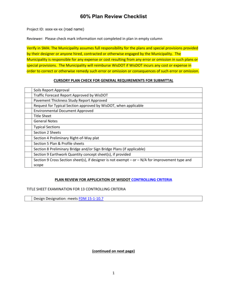
60% Plan Review Checklist Project ID: xxxx-xx-xx (road name) Reviewer: Please check mark information not completed in plan in empty column Verify in SMA: The Municipality assumes full responsibility for the plans and special provisions provided by their designer or anyone hired, contracted or otherwise engaged by the Municipality. The Municipality is responsible for any expense or cost resulting from any error or omission in such plans or special provisions. The Municipality will reimburse WisDOT if WisDOT incurs any cost or expense in order to correct or otherwise remedy such error or omission or consequences of such error or omission. CURSORY PLAN CHECK FOR GENERAL REQUIREMENTS FOR SUBMITTAL Soils Report Approval Traffic Forecast Report Approved by WisDOT Pavement Thickness Study Report Approved Request for Typical Section approved by WisDOT, when applicable Environmental Document Approved Title Sheet General Notes Typical Sections Section 2 Sheets Section 4 Preliminary Right-of-Way plat Section 5 Plan & Profile sheets Section 8 Preliminary Bridge and/or Sign Bridge Plans (if applicable) Section 9 Earthwork Quantity concept sheet(s), if provided Section 9 Cross Section sheet(s), if designer is not exempt – or – N/A for improvement type and scope PLAN REVIEW FOR APPLICATION OF WISDOT CONTROLLING CRITERIA TITLE SHEET EXAMINATION FOR 13 CONTROLLING CRITERIA Design Designation: meets FDM 15-1-10.7 (continued on next page) 1 60% Plan Review Checklist PLAN REVIEW FOR APPLICATION OF WISDOT CONTROLLING CRITERIA (continued) TYPICAL SECTIONS EXAMINATION FOR 13 CONTROLLING CRITERIA Typical Section sheets: Finished sections – (Main line segments, side roads segments & staged construction segments only) Typical Section sheets: All sections agree with WisDOT SE Region approvals of Typical Sections Superelevation (if applicable): meets FDM 11-3, Attachment 5.1, 5.7 Lane Width: meets FDM 11-3, Attachment 5.7, meets FDM 11-15-1.1 & FDM 11-20-1 Shoulder Width: meets FDM 11-3, Attachment 5.8, meets FDM 11-15-1.4 &: FDM 11-20-1 Pavement Cross Slope: meets FDM 11-3, Attachment 5.7, FDM 11-15-1.3, & FDM 11-20-1.1 Horizontal Clearance: meets FDM 11-3, Attachment 5.10, 5.14, FDM 11-15-1.9.2, FDM 11-20-1.9 & FDM 11-35-1. Not noted to be shown per FDM 15-1-15.1 Median Widths, for rural and transitional/high speed urban roadways less than FDM design criteria: meets FDM 11-3, Attachment 5.9, FDM 11-15-1.10, & FDM 11-20-1.4.4 Structural Capacity: facilitates implementation of FDM 11-3, Attachment 5.14, matches approved Environmental Report SIGNALS EXAMINATION FOR 13 CONTROLLING CRITERIA Additional Section 2 sheets: Signals concept plan featuring monotubes location for horizontal and vertical clearance, if applicable: meets FDM 11-3, Attachment 5.2, 5.10 LIGHTING EXAMINATION FOR 13 CONTROLLING CRITERIA Additional Section 2 sheets: Lighting concept plan featuring pole location for horizontal and vertical clearance, if applicable: meets FDM 11-3, Attachment 5.2, 5.10 PLAN & PROFILE EXAMINATION FOR 13 CONTROLLING CRITERIA Horizontal Alignment: meets FDM 11-3, Attachment 5.1 Lane width: meets FDM 11-3, Attachment 5.7, meets FDM 11-15-1.1 & FDM 11-20-1 Shoulder width: meets FDM 11-3, Attachment 5.8, meets FDM 11-15-1.4 &: FDM 11-20-1 Median Widths, for rural and transitional/high speed urban roadways less than FDM design criteria: meets FDM 11-3, Attachment 5.9, FDM 11-15-1.10, & FDM 11-20-1.4.4 Bridge Width: meets FDM 11-3, Attachment 5.14, meets FDM 11-15-1.9.3, & FDM 11-35-1 Vertical Alignment: meets FDM 11-3, Attachment 5.2 Grades: meets FDM 11-3, Attachment 5.2 Stopping Sight Distance: meets FDM 11-3, Attachment 5.1, 5.2, 5.3 Structural Capacity: facilitates implementation of FDM 11-3, Attachment 5.14, matches approved Environmental Report (continued on next page) 2 60% Plan Review Checklist PLAN REVIEW FOR APPLICATION OF WISDOT CONTROLLING CRITERIA (continued) STRUCTURES EXAMINATION FOR 13 CONTROLLING CRITERIA Bridge Width: meets FDM 11-3, Attachment 5.14, FDM 11-15-1.9.3, & FDM 11-35-1 Vertical Clearance: meets FDM 11-3, Attachment 5.2, 5.14 Structural Capacity: meets FDM 11-3, Attachment 5.14, matches approved Environmental Report CROSS SECTION EXAMINATION FOR 13 CONTROLLING CRITERIA Lane Width: meets FDM 11-3, Attachment 5.7, meets FDM 11-15-1.1 & FDM 11-20-1 Shoulder Width: meets FDM 11-3, Attachment 5.8, meets FDM 11-15-1.4 &: FDM 11-20-1 Superelevation (if applicable): meets FDM 11-3, Attachment 5.1, 5.7 Pavement Cross Slope: meets FDM 11-3, Attachment 5.7, meets FDM 11-15-1.3, FDM 11-20-1.1 & Median Widths, for rural and transitional/high speed urban roadways less than FDM design criteria: meets FDM 11-3, Attachment 5.9, FDM 11-15-1.10, & FDM 11-20-1.4.4 Structural Capacity: meets FDM 11-3, Attachment 5.14, matches approved Environmental Report COMMENTS ON NEED FOR ESR COMMENTS 3 60% Plan Review Checklist PLAN REVIEW FOR KEY DESIGN STUDY TITLE SHEET EXAMINATION Title sheet: ID & Project Title to match FIIPs Title sheet : Location map with structures & stationing Title sheet : Design Designation/Traffic information/ Design Speed matches approved PTSR Title sheet : Begin/End project limits (y, x coordinates) TYPICAL SECTION EXAMINATION Existing pedestrian & bicycle facilities shown on main line and sideroads in typical sections Existing median width(s) shown on main line and sideroads in typical sections Existing side-slope(s) and ditch section(s) shown on main line and sideroads in typical sections When the sidewalk is not being fully replaced, is it clear that sidewalk to remain is ADA compliant? Finished pedestrian & bicycle facilities shown on main line and sideroads in typical sections Finished median width(s) shown on main line and sideroads in typical sections Finished side-slope(s) and ditch section(s) shown on main line and sideroads in typical sections PLAN & PROFILE SHEET EXAMINATION Begin/End construction limits, if provided Alignment (mainline and side roads) Horizontal and vertical (calculated) featuring K-value, Degree/radius of curves/superelevation, & percent of grade Slope Intercepts Right-of-way & easements featuring existing and/or new, existing access control, property lines & property owner names Drainage Arrows (direction of flow) Drainage Plan for rural project featuring cross drains (diameter and location), special ditches, berms, channel relocation & structures requiring R/W Drainage Plan for urban project featuring outfalls, trunk line location, & structures requiring R/W Environmentally Sensitive areas Major erosion control consisting of R/W required, retention or sedimentation basins, energy dissipaters, etc.) Separate details or memo if minor Numbered structures (including retaining walls, high mast light, and sign bridges) with type of work defined/notations per FDM, if applicable Existing Utilities Railroads – planned work, if applicable Rock profiles (both rip-able and hard) and marsh profiles, if applicable Existing & proposed access points including type Existing advertising signs, if applicable Maintenance crossovers on multi-lane highways, if applicable 4 60% Plan Review Checklist PLAN REVIEW FOR KEY DESIGN STUDY CROSS SECTION SHEET EXAMINATION Original ground Marsh and rock lines Proposed subgrade or finished grade Cross drains, if provided Sidewalk Curb or Curb & Gutter (Milwaukee County or State) Barrier wall R/W or TLE, PLE Interval (location as needed to determine R/W requirements) for rural projects of 100 to 400 feet featuring entrances (driveways may be half-section), selected locations, & side roads Interval (location as needed to determine R/W requirements) for urban projects of 50 to 100 feet featuring entrances (driveways may be half-section), selected locations, & side roads OTHER SECTION 2 SHEET EXAMINATION General Notes sheet(s): Utility Contacts, DNR Liaison & Diggers Hotline Logo provided Intersection details, if not standard, consistent with FDM 11-25-1. Pertinent information regarding type of intersections and curb ramps as shown in the standard detail drawings shall be shown, unless covered by a general note. ADA requirements must be met (WisDOT SELP special directive) Traffic control concept plan, signals, signing, lighting & construction staging (drawings or memos) Contour Maps with match lines Project Overview ADDITIONAL EXHIBITS EXAMINATION Estimate sheets. 60% plan submittal (Engineer’s estimate, typical + 60% RBQ). Only as detailed as plan Preliminary Earthwork Balance sheet, if provided Commitments or issues of concern which affected design per approved Environmental Document SPECIAL SECTION 2 SHEET PRIORITY ITEMS FOR KEY DESIGN STUDY INTERCHANGE SHEET EXAMINATION Existing interchange type, ramp(s) type, speed-related controlling criteria per FDM 11-30 & FDM 151-20.4, if applicable Finished interchange type, ramp(s) type, speed-related controlling criteria per FDM 11-30 & FDM 15-1-20.4, if applicable 5 60% Plan Review Checklist COMMENTS ON PROJECT ELIGIBILITY FOR START OF FINAL DESIGN: TWO-PARTY DESIGN CONTRACTS IN-DEPTH COMMON PROJECT ELEMENTS FOR COMPLETE DESIGN STUDY TYPICAL SECTIONS EVALUATION Typical Section sheets: Finished sections - material identification and thickness shown to the nearest one-quarter inch matching approved PTSR Clear zone, rural roadways & urban roadways per FDM 11-20-1.9.2 Roundabouts, if applicable Railroad, if applicable PLAN & PROFILE SHEETS EVALUATION Sideroad Names Sideroad approach grades Roundabouts, if applicable Railroad, if applicable COMMENTS ON NEEDS FOR DSR 6 60% Plan Review Checklist IN-DEPTH COMMON PROJECT ELEMENTS FOR COMMENT ON CONSISTENCY WITH FDM TYPICAL SECTIONS EVALUATION Each typical section sheet shall have a title block along the bottom edge of the sheet. The title block shall include the State Project Number(s), space for a sheet number and title Typical Section sheets: Existing sections shown when construction staging work is being done on the pavement or shoulder, the pavement is being removed or the pavement or shoulder is being used to carry traffic A main line typical section shall be shown for all applicable projects. Additional typical sections shall be shown for side roads, ramps, driveways and temporary roads where applicable. Ultimate typical sections are required for all stage construction projects. Scale: The width of section shall be selected to provide clarity of detail Slopes: This is expressed as a ratio of horizontal distance to vertical distance Cross Slope: This is the amount of rise or fall indicated in percent Width: The width of lanes, shoulders, roadbed, ditches, clear zone and median The limits of topsoiling, salvaged topsoiling, fertilizing, seeding or sodding shall be shown Pavement ties, tie bars, underdrains, geotextile fabrics, islands, concrete barriers, removals, etc. shall be shown when they are required in the construction Location Limits: Typical sections shall be titled and stationing limits indicated. Minor equations may be omitted. Station limits need not be shown where there is only one typical section per roadway Vertical and Horizontal Reference: All typical sections shall show the relationship between the typical section and the grade line profile shown on the Plan and Profile Sheet with a point referred to on profile note. The vertical relationship between the typical section and the cross sections shall also be shown by a point referred to on cross section note unless indicated on the Cross Section Sheets Doweled Concrete Pavements: All doweled concrete pavements shall have a notation indicating that dowels are required. Example is: 10-inch Non-reinforced Concrete Pavement (Doweled). Tined Concrete Pavements: All concrete pavements to be tined shall include a notation indicating that tining is required. Example is: 10-inch Non-reinforced Concrete Pavement (Doweled and Tined) A pavement boring log & lab tests shall be provided on the typical section sheet for projects containing the item: Salvaged Asphaltic Pavement. Only log is required for Pulverizing & Relaying Asphaltic 7 60% Plan Review Checklist (CONTINUED) OTHER SECTION 2 SHEETS EVALUATION Construction details are required for bid items that require detailing not covered in the standard detail drawings or other plan elements. There is no standard format for construction details. They should be kept simple and should avoid duplication with standard detail drawings or plan and profile sheets. Choose a scale that will sufficiently display the detail. A title is required for each detail If control points and associated tie points are not shown on an alignment sheet or plan and profile sheet, a construction detail showing these shall be added The plan and profile of storm sewers and utilities shall be shown on detail sheets separate from the plan and profile sheets. The plan view shall show the location of manholes and inlets, existing underground utilities, storm sewers and other information pertinent to the storm sewer system. The profile shall show the existing ground, existing utilities if available, flow line grades, the profile of the storm sewer, manholes and inlets, the size, type and grade of the storm sewer, and the manhole and inlet grades Planting is the furnishing and planting of trees, shrubs, vines, herbaceous plants and special seed mixtures. When planting is included under a contract with other construction operations such as grading, base, paving, etc., the planting shall be shown on detail sheets separate from the plan and profile sheet If the planting is let as a separate contract, the planting layout detail sheets will become the plan sheets Planting layout details shall show the location of plants and plant beds, species and size of plants, the quantity of each planting, root condition and other pertinent planting information. The common name for trees, shrubs and vines shall be used on the planting layout details and shall be referenced to the plant data chart Permanent sign replacement is within the local project agreement? Regarding Type 1 signs: Any signs not conforming to WisDOT and MUTCD policies shall be replaced in the improvement project. Any exceptions to replacement of Type I signs shall be coordinated with the Region Traffic Engineering Supervisor. All corten steel I-beams and bases shall be replaced. Regarding Type 2 signs: FHWA minimum sign retro-reflectivity standards do not permit the usage of Engineer Grade on warning and guide signs. It is also WisDOT policy to not use Engineer Grade on any signs, including regulatory signs. Any exceptions to replacement of Type II signs shall be coordinated with the Region Traffic Engineering Supervisor When permanent signing is included under a contract with other construction operations such as grading, base, paving, etc., the permanent signing shall be shown on signing plan detail sheets separate from the plan and profile sheets If permanent signing is let as a separate contract, the permanent signing layout detail sheets will become the plan sheets Permanent signing layout details shall show the location of sign bridges, sign bridge numbers, new signs, moving signs, removal of existing signs, revision of existing signs, signs being furnished or moved by others, delineators and other pertinent signing information (CONTINUED) 8 60% Plan Review Checklist OTHER SECTION 2 SHEETS EVALUATION (continued) Do not use 4” x 4” wood posts on new permanent sign installations. A pictorial drawing of the signs shall appear on the sign layout sheets. A legend with pictorial drawings on each sign layout sheet is also acceptable. Each sign pictorial drawing shall be designated by standard sign code as shown on the department’s Sign Plate book. Number each sign location on the sign layout sheet to refer to the signing miscellaneous quantities. Show the sign size below the sign code Permanent signing miscellaneous quantities shall show a location referencing the sign to the sign layout sheet; a sign offset distance for Type 1 signs only (if applicable), sign code, sign size, sign message, and all applicable signing and post quantities A detail showing the layout of the overhead sign support in relation to the roadway shall be shown in the construction details of the plan The following information is required on this detail in order for the contractor to fabricate the overhead sign support: The sign sizes and location on the structure as well as their relation to the traffic lanes below. The high point of roadway elevation and the top of concrete base elevation or the relative difference in elevation between the two The required minimum vertical clearance from the high point of the roadway to the low point on the sign/structure. Show signs centered on the horizontal arm Horizontal dimensions of the roadway typical section, including cross slopes The location of the structure by station and, if applicable, by highway and crossroad The identification number of the structure The number of chord elements for the horizontal arm or span. Indicate round chords with web members attached by gusset plates when a two-chord system is used. Refer to FDM 11-55-20 for a discussion of the configuration of the overhead sign support and design limitations For small LED or changeable message signs, show the length x width x thickness and its weight The base design, either site specific or a standard detail drawing State the Fatigue Category, in the case of cantilever overhead sign supports, on the plans 9 60% Plan Review Checklist (CONTINUED) OTHER SECTION 2 SHEETS EVALUATION When lighting is included under a contract with other construction operations such as grading, base, paving, etc., the lighting shall be shown on detail sheets separate from the plan and profile sheets If the lighting is let as a separate contract, the lighting layout detail sheets will become the plan sheets Lighting lay-out details shall show the location of conduits, cables, wires, concrete bases, poles, mast arms, luminaries, transclosures, pull boxes, circuits, pole identification numbers, lighting unit codes, control cabinets, existing electrical facilities and other pertinent lighting information Traffic signal layout details shall be shown on detail sheets separate from the plan and profile sheets The traffic signal detail shall show the location of pull boxes, controllers, concrete bases, conduit, standards, poles, mast arms and loop detectors; the location, arrangement and direction of signal heads; the size of such items as conduit, loop detector, etc; and other pertinent traffic signal information Sequence of operation, controller logic, detector logic and cable layout shall be shown in tabular form When pavement marking is included under a contract with other construction operations such as grading, base, paving, etc., the pavement marking shall be shown on detail sheets separate from the plan and profile sheets If the pavement marking is let as a separate contract, the pavement marking layout detail sheets will become the plan sheets Intersections, gore areas, parking lots, paved medians and lanes with words and arrows are typical areas where pavement marking layout details are required These details shall contain adequate information to layout the pavement marking Traffic control/stage construction details shall be included in all plans except where the necessary information is provided by the standard detail drawings. These details shall be shown on detail sheets separate from the plan and profile sheets. These details shall include the location of traffic control signing, pavement markings, drums, barricades, safety barriers, arrow boards, temporary pavement marking, construction areas, direction of traffic and other pertinent traffic control information The location of established detours shall be shown on the traffic control/stage construction layout details The sign layouts and sign code numbers used in the traffic control layout details shall be in accordance with the Federal Highway Administration Manual of Standard Highway Signs. If a desired sign is not contained in the Manual, then a department sign plate shall be specified The Federal Highway Administration Manual of Standard Highway Signs lists most of the orange background signs commonly used in construction zones with a beginning sign code of "W". However, there are signs with other background colors listed in the Manual with a beginning sign code of "W" that may be used in construction zones. These signs shall be labeled with a beginning code of "WO" The traffic control/stage construction layout details shall include the following notes when appropriate. 1. All signs are 48-inch x 48-inch unless otherwise noted. (This note may be used in place of labeling the size of each sign. Any other size of sign must be individually labeled.) 2. "WO" signs are the same as "W" signs except the background is orange 10 60% Plan Review Checklist (CONTINUED) OTHER SECTION 2 SHEETS EVALUATION Fencing layout details shall be included on projects where the right of way is required to be fenced. The details may be shown on separate detail sheets, combined with other details or shown on the plan sheets. The location of the fence shall be referenced with dimensions to the reference line or right of way line For projects with complex alignment, such as interchanges, a separate alignment detail shall be included The control points shall be shown graphically with Wisconsin State Plane Coordinate System ground coordinates (N,E) or Wisconsin County Coordinate System coordinates (X,Y) so the initial layout construction staking can be performed STRUCTURE SHEETS EVALUATION AFFECTING DESIGN Typical sections for structures are located with the structure plans PLAN & PROFILE SHEETS EVALUATION Profiles are not required for resurfacing, signing, and planting projects A plan and profile sheet is required on most contract plans. An example is illustrated in FDM 15-1 Attachment 5.21 and FDM 15-1 Attachment 6.3. The CADDS and CAiCE programs produce sheets with different borders and title blocks than are shown in the above examples but they are acceptable Each Plan and Profile Sheet shall have a title block that shall include the State Project Number(s) and space for a sheet number. This title block is along the bottom edge of the sheet Scale is governed by the topography to be shown and the complexity of the work The plan shall show the centerline or other reference line of the proposed roadways, side roads, interchange ramps, frontage roads, rest areas, etc Stationing of all roadways shall increase from south to north or west to east based on the cardinal direction of the highway route When multiple alignments are required (ramps, alternate alignments, etc.) an identifier is often used to label each alignment. These alignment identifiers shall consist of 1 or 2 upper case alpha characters – no numeric characters. The format shall show the alignment identifier following the numeric stationing, e.g. 123+45 XX where XX is the alignment identifier Coordinates referenced to the Wisconsin Coordinate System or the appropriate county coordinate system shall be shown for the beginning of all projects. If the centerline was tied to the Wisconsin Coordinate System by a field survey traverse, the coordinates for points of intersection (PI's) and the end of the project shall also be shown Right-of-Way shall be shown. Dimensioning is required only if the right-of-way plat has not been included as part of the plan. The boundaries and dimensions of all construction permits shall be shown. Also show property lines and the names of property owners If the plan sheet is also being used as a right of way plat, see FDM 12-15-5 for additional plan sheet requirements 11 60% Plan Review Checklist (CONTINUED) PLAN & PROFILE SHEETS EVALUATION North arrow shall be shown In order to more readily identify pipelines carrying combustible fluids, the use of the "CAUTION" symbol shown in FDM 15-5 Attachment 30.2, is required on all contract plans. Within the highway right-of-way all pipelines carrying natural, manufactured, or liquefied petroleum gases, or any other combustible or explosive fluids shall be so identified. This includes identifying the location of all flush or below ground appurtenances such as valve and regulator pits Removing culvert notations are required and shall include the station, size, type and disposition of the culvert Public Survey Landmark locations within the right-of-way shall be shown Profiles of both the proposed grade line and existing surface grade shall be shown. The proposed grade line shall be drafted as the dominant line, with the percentage of gradient and vertical curve information shown. All profile stationing shall be shown increasing from left to right on the sheet Proposed grade elevations shall be shown at all 100-foot stations A structure notation including the location, structure number, structure type, span lengths, clear roadway width and skew angle shall be shown on the profile when structures require R/W or numbered Structure notations shall also be included for sign bridges, retaining walls and high mast lighting foundations when structures require R/W or numbered A notation is also required for old structures that are being removed when structures require R/W A culvert notation for cross drains including the location, number, size and skew angle shall be shown on the profile. The graphic location of the culvert shall be drawn on both the plan and profile portions of the sheet Show the location of all earthwork balance points, together with associated earthwork volumes, shrinkage and swell unless a computer earthwork data sheet is provided or sufficient data is given in the earthwork summary in the miscellaneous quantities to cover balance points. If earthwork is to be performed by stages the balances for each stage shall be shown. The earthwork volumes shall be absolute volumes before the shrinkage or swell has been applied. (CONTINUED) CROSS SECTION SHEETS EVALUATION Cross section sheets are required in contract plans that have the following bid items: common excavation, marsh excavation, borrow excavation, rock excavation, & fill being measured in-place The normal cross section interval is the station (100 ft). A 50-ft interval is often used on urban projects Each sheet shall provide a direct reading grid pattern background, either by the use of a weighted dot pattern or a weighted/screened line pattern. An example of the pattern is shown in FDM 15-1 Attachment 5.24 Each cross section sheet shall have a title block along the bottom edge of the sheet. The title block shall include the state project number and space for a sheet number 12 60% Plan Review Checklist Horizontal and vertical graphic scales shall be shown on each cross section sheet in the lower right corner. See table below for 22” by 34” sheets from FDM 15-1 The earthwork block shall contain stationing, absolute volumes for excavation by type, absolute fill volumes and sheet totals or other appropriate totals and subtotals. The excavation shall be tabulated by the bid items used in the contract. If an Earthwork Summary Sheet(s) is shown in the contract plan, the earthwork block may be omitted. The earthwork volumes shall be absolute volumes before the shrinkage or swell has been applied Each cross section shall show the original ground line with a lightweight dashed line and the proposed cross section with a heavy weight solid line The cross sections shall be drawn to show the finished slopes, including any topsoil or salvaged topsoil that will be placed on them Do not show topsoil or salvaged topsoil as separate items in the cross sections Each cross section shall show station location, grade line elevation, proposed centerline, the rightof-way limits on both sides, and datum elevation There shall be a minimum of 1-inch clearance between cross sections Cross sections for divided highways shall be shown on one sheet. If the sheet lacks sufficient width to show the entire cross section at an acceptable scale, the cross section shall be split and offset All lines and data shall be drawn on the front of the sheet and shall be inside the printing borders as defined in FDM 15-5-5 A notation indicating the beginning and ending of common, marsh and rock excavation, as well as the beginning and end of construction, shall be included, when appropriate 13
