Module B3 Problem 1 The 3-phase loads are connected in parallel
advertisement

Module B3
Problem 1
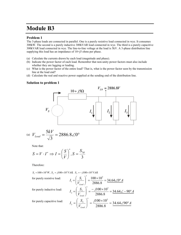
The 3-phase loads are connected in parallel. One is a purely resistive load connected in wye. It consumes
300kW. The second is a purely inductive 300kVAR load connected in wye. The third is a purely capacitive
300kVAR load connected in wye. The line-to-line voltage at the load is 5kV. A 3-phase distribution line
supplying this load has an impedance of 10+j5 ohms per phase.
(a) Calculate the currents drawn by each load (magnitude and phase).
(b) Indicate the power factor of each load. Remember that non-unity power factors must also include
whether they are lagging or leading.
(c) What is the power factor of the entire load? That is, what is the power factor seen by the transmission
line at the load end?
(d) Calculate the real and reactive power supplied at the sending end of the distribution line.
Solution to problem 1
VLN 2886.8V
10 j5
VS
(a)
VLoad
I1
I2
I3
5kV
2886.80
3
Note that:
S
S
S V I I , S 3
3
V
Therefore:
S1 100 103 W , S 2 j100 103 VAR, S 3 j100 103 VAR.
for purely resistive load:
for purely inductive load:
S 100 103
I1 1
34.640 A
2886.8
VLoad
S2 j100 103
I 2
34.64 90 A
2886.8
VLoad
for purely capacitive load:
S3
j100 103
I 3
34.6490 A
2886.8
VLoad
Note in the above that for the resistive load, the current and voltage are in phase, for the inductive, the
current lags by 90 deg, and for the capacitive, the current leads by 90 deg.
(b) Load 1 : pf 1 1.0
Load 2 : pf 2 0 lagging
Load 3 : pf 3 0 leading
VLoad 2886.980
I1 I 2 I3 34.640 j34.64 j34.64 34.640
(c) Need current angle with respect to
I Load
VLoad and I Load are in phase !
pf Load 1.0
so
(d)
Vs VLoad I Load Zt 2886.8 34.640 10 j5 3237.83.07
S3 3Vs I Load
3 3237.83.07 34.640 336,4723.07VA
P3 335 .99 kW , Q3 18 .02 kVAR
Alternatively, one could compute losses and add to load :
Sloss 3 3( I Load Zt ) 334.64 10 j5 35,999.9 j17 ,998.9
2
2
S 3 S load 3 S loss 3 300 10 3 35,997 .9 j17 ,998 .9VA
P3 335 .99 kW
Q3 18 .0kVAR
Problem 2
A three phase load has a per phase impedance, connected in Y, of 100 j30 . The line-to-line voltage
magnitude at the load is 1500V. The three-phase distribution line supplying this load has an impedance of
10 j5 / .
(a) Calculate the line-to-line voltage magnitude at the sending end of the distribution line.
(b) Calculate the real and reactive power supplied at the sending end of the distribution line.
Solution to problem 2
(a)
V AN
V
1500
866.025
866.025V I A AN
7.945 j 2.384 A 8.295 16.7 A
Z LOAD 100 j 30
3
Vsending ,AN V AN I A Z Line 866.0250 8.295 16.7 10 j 5
957.39 j15.89 957.530.95V
VSending ,AB 957.53 3 1658.5V
(b) S 3 V
sending , AN I a 3 957.530.95 8.29516.7 22 ,706.5 j 7224.7VA
P 22 .706 kW , Q 7.225 kVAR
Problem 3
A three-phase load consumes 100kVA at 0.7 pf lagging. The line-to-line voltage magnitude at the load is
1500V. The three-phase distribution line supplying this load has an impedance of 10 j5 /
(a) Calculate the line-to-line voltage magnitude at the sending end of the distribution line.
(b) Calculate the real and reactive power supplied at the sending end of the distribution line.
Solution to problem 3
(a) Note that =cos-1(0.7)=45.57 deg (the angle is positive because the pf is lagging), and sin(45.7)=0.714.
1500
100 103
0.7 j 0.714VA
Van
866.0250V , S1
3
3
S1
33.3 10 3 0.7 j 0.714
I L
38.45 45.57 A
866.025
Van
Vsending ,an Van I L Z L 866.0250 38.45 45.57 10 j 5 1279.2 6.211
Vsending ,AB 3 1279.2 2215.3V
(b)
S sending 3 Van ,sending I L 31279.2 6.211 38.45 45.57 147.55639.36VA
Psending 114.09kW , Qsending 93.58kVAR
Problem 4
The complex power absorbed by a three-phase load is 1500kVA at 0.8 pf lag
P/
Q/
If the Line voltage at the load in problem 1 is 8660.2540 V, what is the voltage magnitude across each
phase of the load, if the load is connected as follows,
Vd
Vy
What is the magnitude of line current drawn by this load?
IL
Solution to problem 4
The complex power absorbed by a three-phase load is 1500kVA at 0.8 pf lag
Note that =cos-1(0.8)=36.87 deg (the angle is positive because the pf is lagging), and sin(36.87)=0.6.
Then P1=1500(0.8)/3=400 kW, Q1=1500(0.6)/3=300 kW.
P1Ø = 400 kW
Q/Ø = 300 kVAR
If the Line voltage at the load in problem 1 is 8660.2540 V, what is the voltage
magnitude across each phase of the load, if the load is connected as follows,
V = 8660.254 V
V y = 5000 V=
8660.254
3
What is the magnitude of line current drawn by this load?
I L = 100 A
IL =
1500 x103
3 8660.254
Problem 5
In the circuit shown below, Van = 12,000 + j 0 V (rms). Assume positive phase sequence. The balanced
source supplies 1.5 MW and 0.3 MVAR to the three phase balanced load. Find:
a) The rms line current.
b) Z p
Aa
15
A
Vcn
Nn
P
Z
Vbn
Solution to problem 5
(a) S3 (1.5 j 0.3) *106VA
+
BC
B
15
VCA
+V
15
Bb
+
VAB
ZP
Van
ZP
C
1
S1 ( 1.5 j 0.3 )* 106VA
3
*
*
Van I an S1 12,000 I an
( 1.5 j 0.3 )x106
*
I an
42.49211.31 A
3 12,000
I an 42.492 11.31 A
(b) Z p 3Z py
Z py
Van
I aA
VAN VaN I aA * 15 12,000 42.492 11.31* 15
11,375.680.6296V
11,375.680.6296
267.713511.939
42.492 11.31
3x267.713511.939 803.140511.939
Z Py
Z Py
Problem 6
A three phase source is supplying a balanced three phase load over a transmission line having impedance of
ZL=2+j20 ohms per phase. The voltage at the source end of the transmission line is 2887 0 volts line to
neutral. The current supplied through the transmission line is IL=100 -30 amperes.
1. Determine the power factor seen by the source, and specify whether it is leading or lagging.
2. Determine the voltage (line to neutral) at the load.
3. Determine the power factor of the load, and specify whether the load is
a. leading or lagging
b. inductive or capacitive
4. Determine the real and reactive power consumed by the load.
Solution to problem 6
1.
pf=cos(30)=0.8660, and it is lagging.
2.
VLOAD=28870-100-30(2+j20)=713.8-j1632=2366.5-43.6
3.
pf angle=angle at which voltage leads the current=-43.6-(-30)=-13.6, so pf=cos(-13.6)=0.972, …and
the current is leading the voltage! This means the power factor is leading (part a) and the load must be
capacitive (part b).
4.
S=3VLOAD (I)*=3(2366.5-43.6)(100+30)=690044-j166939=709.950-13.6 kVA
Problem 7
A balanced, three-phase load having a power factor of 0.8 lagging is supplied by a transmission line
carrying 300 amps at 115 kV line-to-line. Compute the three-phase real and reactive power delivered to the
load.
Solution to problem 7
S3
3 VLL I
3 115 10 300 59.756MVA
3
pf 0.8 cos 1 0.8 36.9 sin 0.6
P (59.756) (0.8) 47.8MW
Q (59.756) (0.6) 35.879 MVAR
Problem 8
A balanced, three-phase, delta-connected load consumes 50-j20 kVA at a line-to-line voltage of 13.8 kV.
Compute the per-phase impedance of this load assuming a series connection between R and X.
Solution to problem 8
2
2
VLL
VLL
( 13.8 103 )2
S * Z *
3283 j1313
3
Z
S
( 50 j 20 ) 10
Z 3 ZY Z 3 ( 3283 j1313 ) 9849 j 3939
R 9849
X 3939( Capacitive )
Problem 9
A three-phase wye-connected load having impedance of Z1=200+j50 ohms per phase is connected in
parallel with a three phase delta-connected load having impedance of Z2=600+j300 ohms per phase. The
load is supplied by a three-phase wye-connected generator that is directly interconnected with the loads
(i.e., there is no transmission line between the generator and the loads). The voltage magnitude of the
generator is 13.8 kV line-to-line. Assume that the phase to neutral voltage at the generator is the angle
reference.
1. Draw the three-phase circuit. Clearly identify the numerical values of one line to neutral source voltage
phasor and one-phase impedance for each of loads 1 and 2.
2. Draw the per-phase circuit. Clearly identify the numerical values of the source voltage phasor and the
per-phase impedances of loads 1 and 2.
3. Compute the three-phase complex power consumed by each load and the total, complex three-phase
power consumed by the two loads.
4. Show that the total, complex three-phase power consumed by the two loads can be computed using the
line current and the line-to-line value of the source voltage.
Solution to problem 9
1.
VAN=
7967v
Z1=200+j50
Z2=600+j300
2.
VAN=
7967v
3.
Z1=200+j50
Z2=200+j100
We could use S1 =3|VAN|2/Z1* , S2 = 3|VAN|2/Z2* , or we could get the current instead. Let’s do
it by getting the current.
I1=VAN/Z1=7967/(200+j50)= 37.4918 - j9.3729,
S1=3VAN(I1)*=3(7967)( 37.4918 + j9.3729)= (896.09 +j224.02)kva
P1=896.1 kW, Q1=224.0 kVAR
I2=VAN/Z2=7967/(200+j100)= 31.8680 -j15.9340
S2=3VAN(I2)*=3(7967)(31.8680 +j15.9340)= (761.68e+j380.84)kva
P2=761.7 kW, Q2=380.8 kVAR
STotal=S1+S2=1657.8+j604.86
PTotal=1657.8 kW, QTotal=604.9 kVAR
IT=I1+I2= 69.3598 -j25.3069= 73.83 -20.05, |VLine|=13,800
STotal=(3)(13,800)(73.83){cos(20.05)+jsin(20.05)}= 1657.8+j604.9
4.
Problem 10
Consider a balanced three-phase source supplying a balanced Y- or - connected load with the following
instantaneous voltages and currents.
v an 2 V p cos(t v )
ia 2 I p cos(t i )
vbn 2 V p cos(t v 120)
ib 2 I p cos(t i 120)
vcn 2 V p cos(t v 240)
ic 2 I p cos(t i 240)
where |Vp| and |Ip| are the magnitudes of the rms phase voltage and current, respectively. Show that the total
instantaneous power provided to the load, as the sum of the instantaneous powers of each phase, is a
constant.
Solution for Problem 10
Consider a balanced three-phase source supplying a balanced Y- or - connected load with the following
instantaneous voltages
v an 2 V p cos t v
vbn 2 V p cos t v 120
vcn 2 V p cos t v 240
For a balanced load the phase currents are
ia 2 I p cos t i
ib 2 I p cos t i 120
(2.41)
ic 2 I p cos t i 240
where V p and I p are the magnitudes of the rms phase voltage and current, respectively. The total
instantaneous power is the sum of the instantaneous power of each phase, given by
p3 v an ia vbn ib vcn ic
Substituting for the instantaneous voltages and currents
p3 2 V p I p cos t v cos t i
cos t
240 cos t
240
2 V p I p cos t v 120 cos t i 120
2V p I p
v
i
Using the trigonometric identity cosx cosy =cos(x-y) + cos(x+y)
p3 V p I p cos v i cos2 t v i
cos
cos2 t
480
V p I p cos v i cos 2 t v i 240
Vp I p
v
i
v
i
The three double frequency cosine terms are out of phase with each other by 120 and add up to zero, and
the three-phase instantaneous power is
p3 3V p I p cos
v i
is the angle between phase voltage and phase current or the impedance angle.
Problem 11
A three-phase line has an impedance of 2+j4 ohms/phase, and the line feeds two balanced three-phase loads
that are connected in parallel. The first load is Y-connected and has an impedance of 30+j40 ohms/phase.
The second load is delta-connected and has an impedance of 60-j45 ohms/phase. The line is energized at
the sending end from a three-phase balanced supply of line voltage 207.85 volts. Taking the phase voltage
Va as reference, determine:
a. The current, real power, and reactive power drawn from the supply.
b. The line voltage at the combined loads.
c. The current per phase in each load.
d. The total real and reactive powers in each load and the line.
Solution for Problem 11
(a) The -connected load is transformed into an equivalent Y. The impedance per phase of the equivalent
Y is
60 j 45
20 j15
3
Z2
The phase voltage is
V1
207.85
3
120 V
The single-phase equivalent circuit is shown in the following figure.
The total impedance is
Z 2 j4
30 j 4020 j15
30 j 40 20 j15
2 j 4 22 j 4 24
with the phase voltage V an as reference, the current in phase a is
V1 1200
I
5A
Z
24
The three-phase power supplied is
S 3V1 I * 3 1200 50 1800 W
(b) The phase voltage at the load terminal is
V2 1200 2 j 4 50 110 j 20
111.8 10.3 V
The line voltage at the load terminal is
V2ab 330 V2 3111.819.7 193.6419.7 V
(c) The current per phase in the Y-connected load and in the equivalent Y of the load is
V2 110 j 20
1 j 2 2.236 63.4 A
Z1 30 j 40
V
110 j 20
I2 2
4 j 2 4.47226.56 A
Z2
20 j15
The phase current in the original -connected load, i.e., I ab is given by
I1
I ab
I2
3 30
4.47226.56
3 30
2.58256.56 A
(d) The three-phase power absorbed by each load is
3111.8 10.3 4.472 26.56 1200 W - j900 var
S1 3V2 I1* 3 111.8 10.3 2.23663.4 450 W j 600 var
S 2 3V I
*
2 2
The three-phase power absorbed by the line is
S L 3RL jX L I
2
32 j 45 150 W j 300 var
2
It is clear that the sum of load powers and line losses is equal to the power delivered from the supply, i.e.,
S1 S 2 S L 450 j600 1200 j900 150 j300
1800 W j 0 var
Problem 12
A three-phase line has an impedance of 0.4+j2.7 ohms per phase. The line feeds two balanced three-phase
loads that are connected in parallel. The first load is absorbing 560.1kVA at 0.707 power factor lagging.
The second load absorbs 132 kW at unity power factor. The line-to-line voltage at the load end of the line is
3810.5 volts. Determine:
a. The magnitude of the line voltage at the source end of the line.
b. Total real and reactive power loss in the line.
c. Real power and reactive power supplied at the sending end of the line.
Solution for Problem 12
(a) The phase voltage at the load terminals is
V2
3810.5
3
2200 V
The total complex power is
S R 3 560.10.707 j 0.707 132 528 j 396
66036.87 kVA
With the phase voltage
I
S
*
R 3
3V2*
V2 as reference, the current in the line is
660,000 36.87
100 36.87 A
3 22000
The phase voltage at the sending end is
V1 22000 0.4 j 2.7100 36.87 2401.74.58 V
The magnitude of the line voltage at the sending end of the line is
V1L 3 V1 3 2401.7 4160 V
(b) The three-phase power loss in the line is
S L 3 3R I j 3 X I
2
2
30.4100 j 3 2.7 100
2
2
12 kW j81 kvar
(c) The three-phase sending power is
S S 3 3V1 I * 3 2401.74.58 10036.87 540 kW j 477 kvar
It is clear that the sum of load powers and the line losses is equal to the power delivered from the supply,
i.e.,
S S 3 S R 3 S L 3 528 j 396 12 j81 540 kW j 477 kvar


