SEISMIC PROTECTIVE SYSTEMS
advertisement
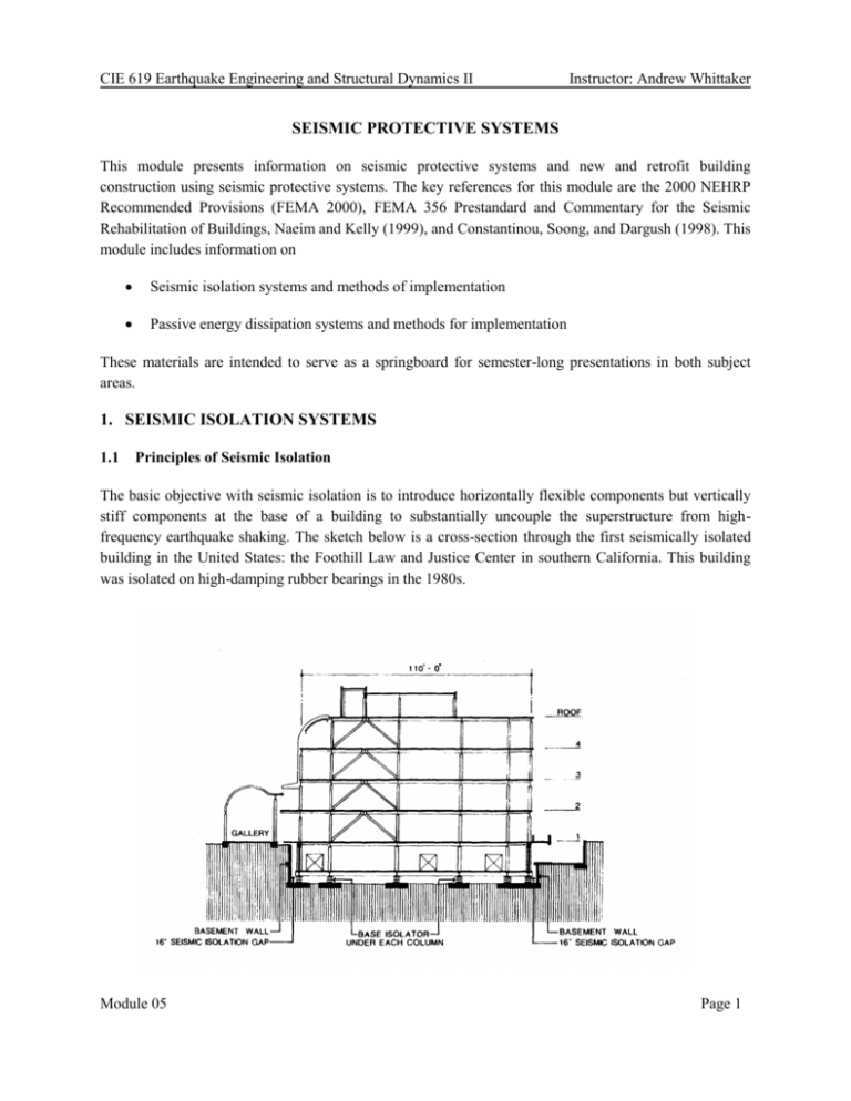
CIE 619 Earthquake Engineering and Structural Dynamics II Instructor: Andrew Whittaker SEISMIC PROTECTIVE SYSTEMS This module presents information on seismic protective systems and new and retrofit building construction using seismic protective systems. The key references for this module are the 2000 NEHRP Recommended Provisions (FEMA 2000), FEMA 356 Prestandard and Commentary for the Seismic Rehabilitation of Buildings, Naeim and Kelly (1999), and Constantinou, Soong, and Dargush (1998). This module includes information on Seismic isolation systems and methods of implementation Passive energy dissipation systems and methods for implementation These materials are intended to serve as a springboard for semester-long presentations in both subject areas. 1. SEISMIC ISOLATION SYSTEMS 1.1 Principles of Seismic Isolation The basic objective with seismic isolation is to introduce horizontally flexible components but vertically stiff components at the base of a building to substantially uncouple the superstructure from highfrequency earthquake shaking. The sketch below is a cross-section through the first seismically isolated building in the United States: the Foothill Law and Justice Center in southern California. This building was isolated on high-damping rubber bearings in the 1980s. Module 05 Page 1 CIE 619 Earthquake Engineering and Structural Dynamics II Instructor: Andrew Whittaker The benefits of adding a horizontally compliant system at the foundation level of a building can be seen below using an acceleration response spectrum. What percentage reduction can be achieved? Increasing the period of the structure reduces the spectral acceleration for typical earthquake shaking. Is this good? Effect on non-structural components? What is the effect on the displacement response of the structure? Consider the displacement spectrum below. For an isolated period of 3 seconds and 5% damping, what is the expected displacement response of the isolated building? Module 05 Page 2 CIE 619 Earthquake Engineering and Structural Dynamics II Instructor: Andrew Whittaker Does the increase in displacement response lead to more damage in the building superstructure? If not, why not? What is the assumed displaced shape of the building frame below: a simple two story two-bay frame supported on three isolators? Most of the displacement in an isolated building occurs over the height of the isolators and there is generally little deformation in the superstructure Isolators must be designed to support gravity (and earthquake-induced) loads AND accommodate large lateral displacements. Displacements in isolated structures are often large and efforts are made to add energy dissipation or damping in the isolation system to reduce displacements. What effect does this have on the displacement response? Consider the displacement response spectrum of the previous page. The addition of energy dissipation to the isolation systems serves to reduce displacements in the seismic isolators, which can translate into smaller isolators, reduced costs, etc. Energy dissipation can be added Internal to the isolator (lead core, specially compounded rubber, friction) External to the isolator (viscous dampers, lead dampers [Japan]) Module 05 Page 3 CIE 619 Earthquake Engineering and Structural Dynamics II 1.2 Instructor: Andrew Whittaker Types of Seismic Isolation Hardware 1.2.1 Introduction There are two common types of large-displacement capacity base or seismic isolation hardware in the United States at this time. 1.2.2 Elastomeric bearings Natural rubber and filled rubber bearings Lead-rubber bearings Sliding bearings Elastomeric Bearings Elastomeric, non-lead-rubber bearings are available as either low-damping natural rubber bearings (manufactured principally by Andre, Bridgestone, DIS, and SEP) or high-damping (filled) bearings (manufactured principally by Andre and Bridgestone). A part-plan and section through a Bridgestone high-damping rubber bearing is presented in the figure below. The maximum shear-strain range for highdamping rubber bearings vary as a function of compound and manufacturer but is generally between 200% and 350%. Module 05 Page 4 CIE 619 Earthquake Engineering and Structural Dynamics II Instructor: Andrew Whittaker Note that the end-plate details in Bridgestone bearings tend to be different from those of Andre and DIS bearings. What are the key construction features of this bearing? What role to the steel shims play in the performance of elastomeric bearings? How are elastomeric bearings constructed? Module 05 Page 5 CIE 619 Earthquake Engineering and Structural Dynamics II Instructor: Andrew Whittaker Energy dissipation in high-damping rubber bearings is achieved by special compounding of the elastomer. Damping ratios will generally range between 7% and 14% of critical. The shear modulus of high-damping elastomers generally ranges between 50 psi and 200 psi. Techniques to engineer mechanical properties are generally considered proprietary. The effective stiffness (a function of the modulus, bonded area, and total rubber thickness) and damping of an elastomeric bearing will depend on Elastomer (including fillers) and vulcanization profile Contact pressure (supported load divided by bonded area) Velocity of loading Load history Strain history Temperature (especially below 20º F) The behaviors of many high-damping elastomers are complex and isolators constructed with these materials are not amenable to simple modeling using standard plasticity or Bouc-Wen formulations. Consider the sample data below from the PhD thesis of Clark from tests of small-scale high-damping (HD) elastomeric bearings. Note that these data are not necessarily indicative of the response of all highdamping rubber bearings. Each elastomer should be carefully studied to assess its dependence on the variables listed above. Consider first data from dynamic cyclic tests of a HD bearing up to shear strains of 250 percent. The contact pressure is approximately 500 psi (low by current standards). Observations? Module 05 Page 6 CIE 619 Earthquake Engineering and Structural Dynamics II Instructor: Andrew Whittaker Now consider tests of the same bearing at shear strain levels between 200% and 350%. Observations? Below are data from tests of two bearings with properties that are identical to those of the bearing shown above. The tests are to a shear strain of 273%. Note the significant difference between the first and thirdcycle response in both cases: this phenomenon is known as scragging. Is the first cycle behavior recoverable with time? Must assume yes. Data support this conclusion. How to account for this wide variation in design of isolation systems? Bounding analysis Module 05 Page 7 CIE 619 Earthquake Engineering and Structural Dynamics II Instructor: Andrew Whittaker High-damping (HD) elastomeric bearings are often characterized as linear viscoelastic components with an effective stiffness and a viscous damping ratio. The data below from Clark shows measured variations in material properties as a function of axial pressure and loading frequency (velocity). How should an engineer account for these wide variations in material properties? Bounding analysis Property modification factor approach to be included in 2003 NEHRP Recommended Provisions 1.2.3 Lead Rubber Bearings Elastomeric, lead-rubber bearings are manufactured in the United States by Dynamic Isolation Systems (DIS) and Seismic Energy Products (SEP). A cut-away view through a DIS lead rubber (LR) bearing is presented in the figure below. Shown in this figure are the Alternating layers of elastomer and steel shims Central lead core Lead-rubber bearings are generally constructed with low-damping (unfilled) elastomers (with shear moduli in the range of 85 to 100 psi at 100% shear strain) and lead cores with diameters ranging between Module 05 Page 8 CIE 619 Earthquake Engineering and Structural Dynamics II Instructor: Andrew Whittaker 15% and 33% of the bonded diameter of the bearing. The elastomer provides the isolation component and the lead core provides the energy dissipation or damping component. The maximum shear-strain range for lead- rubber bearings varies as a function of manufacturer but is generally between 125% and 200%. The steel shims play another important role in lead-rubber bearings, namely Confinement of the lead core Because (a) lead-rubber (LR) bearings are generally constructed with a low-damping natural rubber elastomer and (b) the maximum shear strain rarely exceeds 200%, many of the variations in response that are characteristic of HD rubber bearings (scragging, load history, strain history, velocity) are not characteristic of LR bearings. [Note however that if a highly filled elastomer is used in lieu of natural rubber in a LR bearing, all of the issues identified earlier for HD rubber bearings must be considered in the assessment of the LR bearing.] The central lead core (or plug) in a LR bearing will dominate the response of the bearing (for typical lead-core diameters), especially if the shear strains are small. Of importance are the mechanical characteristics of the lead comprising the core. The yield point of lead is a function of Temperature 18 MPa, 10 MPa, and 7 MPa at 25ºC, 25ºC, and 25ºC, respectively Confinement that is provided by the steel shims and the top and bottom plate Values of the yield point are often larger in small-scale bearings (say 2000 to 2500 psi) than in full-size bearings (1000 psi to 1500 psi). The guidance of a manufacturer should be sought prior to sizing lead cores in LR bearings. One issue that should be considered in judging the response of LR bearings is the response of the lead core with repeated cycling. Consider the HITEC tests of two LR bearings, each rated to 750 kips of axial load by the vendors: DIS and Skellerup, respectively. Module 05 Page 9 CIE 619 Earthquake Engineering and Structural Dynamics II Instructor: Andrew Whittaker a1. DIS LR bearing b1. Skellerup LR bearing a2. 10-cycle dynamic response b2. 10-cycle dynamic response a3. 3-cycle static response b3. 3-cycle static response Module 05 Page 10 CIE 619 Earthquake Engineering and Structural Dynamics II Instructor: Andrew Whittaker Such response, as noted above is a function of temperature and confinement. Under repeated cycling, the temperature of the lead core rises and its yield point diminishes: substantially altering the hysteresis of the bearing. Although the two bearings shown above have identical rated loads, the lead cores in each bearing are quite different in size: 4.75 inches in diameter in the DIS bearing and 6.5 inches in diameter in the Skellerup bearing. The volume of the Skellerup lead core is nearly twice that of the DIS lead core. Also, the DIS bearing was constructed with 33 internal 0.12-inch thick internal shims whereas the Skellerup bearing was constructed with 24 internal 0.12-inch thick internal shims. Consider first the figures a2 and b2 above. The effective yield point of the Skellerup bearing is substantially greater than that of the DIS bearings and the energy dissipated in the Skellerup bearing is much greater than that in the DIS bearing. Such differences can be attributed to the larger lead core in the Skellerup bearing. The change in hysteresis of the Skellerup bearing is also much grater than that in the DIS bearing with repeated cycling. Why? Consider now figures a3 and b3 above: static tests to 118% and 152% shear strain, respectively. Figure a3 exhibits some level of pinching that is likely a function of partial disengagement of the small diameter lead core (16% of the bonded diameter). Little change in hysteresis shape can be seen with repeated (slow) cycling. Figure b3 shows little evidence of pinching but a significant change in hysteresis that is likely related to the confinement of the lead core (26% of the bonded diameter). How should these variations in material properties be accounted for in design? Bounding analysis Property modification factor approach to be included in 2003 NEHRP Recommended Provisions 1.2.4 Sliding Bearings Sliding seismic isolation bearings are manufactured in the United States by Earthquake Protection Systems (EPS) and R. J. Watson, Inc. EPS manufacture the Friction Pendulum (FP) bearing and R.J. Watson manufacture the Eradiquake bearing. The Eradiquake bearing is widely used on East Coast bridges where the displacement demands are small. The FP bearing is used for both buildings and bridges and has large displacement capacity. Because the focus of this presentation is on isolation hardware for buildings, the discussion below is limited to FP bearings. A cut-away view through a FP bearing is presented in the figure below. Module 05 Page 11 CIE 619 Earthquake Engineering and Structural Dynamics II Instructor: Andrew Whittaker Shown in this figure are Concave dish and housing plate (that are typical ductile cast iron) Articulated slider (typically of 304 stainless steel) Bearing material (high load-low friction composite) Not shown is the stainless steel inlay that is placed (and sometimes attached to) atop the concave dish. The sliding interface plays a crucial role in the response of the FP bearing. The frictional resistance of the interface is a function of Slider diameter (effecting the confinement of the composite) Contact pressure Sliding velocity Temperature Wear (due to extended travel in bridge bearings due to thermal cycling) Some general trends can be observed in the figures below. Note that these trends apply to all PTFE-base composites (similar in part to the composites used in FP bearings). Consider first the general relationship between coefficient of friction, sliding velocity, and contact pressure from Tsopelas et al. (1999). What are the trends evident in this figure? Coefficient of friction as a function of velocity Module 05 Page 12 CIE 619 Earthquake Engineering and Structural Dynamics II Instructor: Andrew Whittaker Effect of pressure One key issue is the threshold value of the sliding velocity beyond which the coefficient of friction does not substantially change. Why? Data for one PTFE-based composite sliding on stainless steel are presented below that shows the frictionvelocity relationship. What conclusions can be drawn for this interface? Module 05 Page 13 CIE 619 Earthquake Engineering and Structural Dynamics II Instructor: Andrew Whittaker What is response for higher velocities? Consider the data below, also from Tsopelas et al. Similar trends at room temperature were reported by Mosqueda et al. following tests on FP bearings at Berkeley. At high velocities (greater than 20 inches per second), the sliding coefficient of friction appears to drop. Why? A substantial increase in temperature at the sliding interface leads to a drop in the coefficient of friction. What is the effect of low operating temperature and why does the coefficient of friction drop so substantially with an increase in velocity? Shown below are data from the HITEC tests of one FP bearing that was rated for an axial load of 750 kips (identical to the rating of the LR bearings described above). Figure c1 shows a section and a plan of the bearing. Data from a high-speed cyclic test are shown in Figure c2. Why is the first cycle response different from that of the second and third cycles? Inertial effects in the HITEC testing machine at the start of testing Virgin travel of the composite over stainless steel overlay Little evidence of stick-slip behavior at corners of hysteresis loop Data from a low-speed cyclic test are shown in Figure c3. The inertial effects evident in Figure c2 are not seen in the low-speed tests. Module 05 Page 14 CIE 619 Earthquake Engineering and Structural Dynamics II Instructor: Andrew Whittaker c1. FP bearing c2. 10-cycle dynamic response c3. 3-cycle static response How should these variations in material properties be accounted for in design? Bounding analysis Property modification factor approach to be included in 2003 NEHRP Recommended Provisions 1.3 Mechanical Characteristics of Seismic Isolation Bearings Seismic isolation bearings are generally characterized as either Linear viscoelastic components Binlinear components Module 05 Page 15 CIE 619 Earthquake Engineering and Structural Dynamics II Instructor: Andrew Whittaker As linear viscoelastic components, isolators are characterized by, Effective stiffness at selected displacement Equivalent viscous damping ratio For this calculation, the effective stiffness and equivalent viscous damping ratio are calculated as keff F F d d and 1 WD 2 k d 2 eff As bilinear components, isolators are characterized by the idealized loop shown below, with zerodisplacement force intercept Qd and second-slope stiffness K d . Module 05 Page 16 CIE 619 Earthquake Engineering and Structural Dynamics II Instructor: Andrew Whittaker High-damping rubber bearings are generally modeled as linear viscoelastic components, where the effective horizontal stiffness of the isolation bearing is given by keff GAb Tr GAb ntr where G is the shear modulus of the elastomer at the shear strain and axial pressure under consideration, Ab is the bonded area, Tr is the total thickness of rubber, n is the number of individual rubber layers, and t r is the thickness of one rubber layer. Lead-rubber bearings are generally modeled as bilinear components, where the zero-displacement force intercept can be estimated as Qd Al y and the second-slope stiffness can be estimated as Kd GAb Tr GAb ntr where Al is the area of the lead core, y is the yield stress of the lead core, and all other terms have been defined previously. Friction bearings are generally modeled as bilinear components, where the zero-displacement force intercept can be estimated as Qd W and the second-slope stiffness can be estimated as Kd W R where is the coefficient of friction, W is the supported weight, and R is the radius of curvature of the sliding surface. The above equations facilitate the preliminary sizing of elastomeric and sliding isolators. Many additional checks must be performed by either the manufacturer or the engineer to characterize isolators sufficiently for final design, including checks for isolator buckling and maximum strain (elastomeric bearings), and minimum component thickness (sliding bearings). Such checks are beyond the scope of this class but will be covered in the Fall class on seismic isolation. Module 05 Page 17 CIE 619 Earthquake Engineering and Structural Dynamics II 1.4 Instructor: Andrew Whittaker Analysis and Design of Seismic Isolation Systems 1.4.1 Introduction Procedures for the analysis and design of seismic isolation systems are available in the 2000 NEHRP Recommended Provisions (for new construction) and FEMA 356 (for retrofit construction). The procedures presented in the two documents are most similar because the same key people prepared both documents. The presentation that follows draws heavily on FEMA 356 because the two-column format in that document is more compact than the one-column format of the 2000 NEHRP Recommended Provisions. Isolation is used for buildings where the performance level is operational or functional following a major earthquake. The procedures of 2000 NEHRP and FEMA 356 assume No damage to the superstructure in the design earthquake Adequate performance (ability to support gravity loads and sustain aftershocks) of the seismic isolators in the maximum earthquake The 2000 NEHRP Recommended Provisions and FEMA 356 support four methods of analysis of isolation systems, namely, Linear static Linear response-history (rarely used) Response-spectrum Nonlinear response history increasing level of rigor Linear and nonlinear analysis of isolation systems per 2000 NEHRP or FEMA 356 generally assume that the force-displacement response of the isolation system can be characterized by the hysteresis loop shown below. Module 05 Page 18 CIE 619 Earthquake Engineering and Structural Dynamics II 1.4.2 Instructor: Andrew Whittaker Linear Static Analysis The linear static method of analysis should be used for the preliminary design of all isolation systems and can be used for the final design of isolation systems that can be loosely characterized as linear viscoelastic (effective stiffness and equivalent viscous damping). Such systems include For linear static analysis, the hazard is defined using the standard NEHRP horizontal response spectrum (see Module 02). See the figure below. The effect of damping is captured using BS and B1 as discussed in Module 02. For completeness, the damping coefficients BS and B1 of FEMA 356 are presented below as a function of the effective damping . Module 05 Page 19 CIE 619 Earthquake Engineering and Structural Dynamics II Instructor: Andrew Whittaker How are the isolators modeled for linear static analysis? As linear viscoelastic components with Effective stiffness at selected displacement Equivalent viscous damping ratio The key step in the static analysis is the calculation of the displacement of the isolation system in the design and maximum earthquakes. Below are excerpts from FEMA 356. Module 05 Page 20 CIE 619 Earthquake Engineering and Structural Dynamics II Module 05 Instructor: Andrew Whittaker Page 21 CIE 619 Earthquake Engineering and Structural Dynamics II Instructor: Andrew Whittaker Limitations on the use of the static method are listed in Section 9.2.3.3 of FEMA 356 and Section 13.2.5.2 of the 2000 NEHRP Recommended Provisions. The method can be used if The isolated building is located at a site with S1 0.6 Isolated building is located on Class A, B, C, or D site Isolated building is low rise (less than 65 ft in height) and regular Effective period at maximum displacement is less than 3 seconds Factor of 3 difference between the fixed base and isolated superstructure periods Isolation system is not too nonlinear; has restoring force; has force-deflection properties independent of the rate of loading, vertical loading, and bilateral loading; and does not have a displacement restraint. 1.4.3 Response-Spectrum Analysis Response-spectrum analysis is often used when the limitations on the static method cannot be met, namely To capture higher-mode effects (reflected through the 65 ft height limit on the static method) If the effective period at the maximum displacement is greater than 3 seconds If the superstructure framing is irregular Linear viscoelastic characterizations of the isolators are used in the mathematical model of the isolated building. The 2000 NEHRP Recommended Provisions and FEMA 356 limit the use of the response-spectrum procedure such that the Isolation system must have a restoring force Isolator behavior is independent of rate of loading and vertical load Isolators have no displacement restraint The isolator not too nonlinear The damping in the isolation system is less than or equal to 30% of critical Module 05 Page 22 CIE 619 Earthquake Engineering and Structural Dynamics II Instructor: Andrew Whittaker Unless the isolators and the isolation system can meet all of the above requirements, nonlinear responsehistory analysis must be used. Further, if response-spectrum analysis is used, Orthogonal earthquake shaking effects must be considered for displacement and force calculations Total design and total maximum displacements cannot be less than a selected percentage of those displacements calculated using the linear static method Component actions cannot be less than a selected percentage of those actions calculated using the linear static method 1.4.4 Nonlinear Dynamic Analysis Nonlinear dynamic analysis can be used for all isolation systems regardless of height, size, geometry, location, and nonlinearity of the isolation system, and must be used when the limits set forth on the linear static and response-spectrum procedures cannot be met. For such analysis, the seismic isolation bearings are modeled explicitly as nonlinear components, often using the bilinear representation of Section 1.3 above. Bi-directional earthquake inputs should be considered for nonlinear response-history analysis and coupled plasticity or Bouc-Wen models should be used to capture the response of the individual isolators Such models work well for lead-rubber and FP bearings High-damping rubber bearings cannot be modeled well with such models 1.4.5 Property Modification Factors Components of elastomeric and sliding seismic isolation bearings are constructed with materials whose properties can change over the life span of the isolated structure. Such variations in material properties should be considered in the design of the isolation system. The property modification factor approach that was developed by Constantinou can be used for this purpose and such an approach can/will be found in 1999 AASHTO Guide Specification for Seismic Isolation Design 2003 NEHRP Recommended Provisions For elastomeric bearings, consideration should be given to Scragging, Aging, Velocity, Temperature For sliding bearings, consideration should be given to Contamination, Aging, Velocity, Temperature, Wear Module 05 Page 23 CIE 619 Earthquake Engineering and Structural Dynamics II Instructor: Andrew Whittaker How are such changes in material properties considered in AASHTO and what is proposed for the 2003 NEHRP Recommended Provisions? s max c i max s min c i min For linear viscoelastic isolation bearings, the effective stiffness would have to be increased and decreased s s from the target range by max and min , respectively, and bounding analysis undertaken to calculate maximum displacements and forces. For bilinear systems, the values of *s would have to be calculated for the zero-displacement force intercept and the second-slope stiffness and then applied to the target ranges for both variables to enable bounding analysis to be undertaken to calculate maximum displacements and forces. 1.4.6 Additional Design Considerations Superstructure design The design of isolated superstructures is based (for new construction) on the forces developed in the isolation system during the design earthquake Force distribution over the height of the building Framing must stay essentially elastic (strength or LRFD design) Ductile detailing is required. Why? What is the expected response of the superstructure in the maximum earthquake? Design and detailing of an isolation system must account for the large displacements that develop across the isolation interface. Some of the considerations are Displacement capacity of non-structural components that cross the isolation plane Displacement capacity around the isolation superstructure (moat) Second-order ( P ) effects on the framing immediately above and below the isolators Module 05 Page 24 CIE 619 Earthquake Engineering and Structural Dynamics II Instructor: Andrew Whittaker Connection of the isolation bearing to the superstructure and substructure A significant challenge for seismic retrofit using isolation 1.5 Seismic Isolation for Rehabilitation and Retrofit To date seismic isolation has been employed for new and retrofit construction. For retrofit construction, isolation has been traditionally limited to historical buildings because conventional retrofit would have destroyed too much historic fabric. Examples of retrofit of historic buildings using base isolation are San Francisco City Hall (lead-rubber bearings) Oakland City Hall (lead-rubber bearings) Los Angeles City Hall (high-damping rubber bearings) US Court of Appeals (Friction Pendulum bearings) Other retrofit applications include museums, data centers and web-hosting centers, such as the AboveNet building in San Francisco, which is discussed below. The biggest challenge facing those tasked with retrofitting a building using seismic isolation relates to installation of the seismic isolation bearings. The AboveNet facility is a low-rise building that was used for production of battle tanks immediately following the Second World War. The lateral stiffness and strength of the building were substantial, making it an ideal candidate for seismic isolation. The client demanded post-earthquake functionality from the facility, which could only be delivered with seismic isolation. The engineer-of-record selected FP bearings for this project. Sample information from the retrofit construction is presented below. Artist’s rendering of the building: http://overlord.eng.buffalo.edu/ClassHomePages/cie619/Lectures/rendering.tif Aerial view of building: http://overlord.eng.buffalo.edu/ClassHomePages/cie619/Lectures/Aerialview.jpg Exterior view of building: http://overlord.eng.buffalo.edu/ClassHomePages/cie619/Lectures/Exterior.jpg Basement construction work showing column reinforcement: http://overlord.eng.buffalo.edu/ClassHomePages/cie619/Lectures/basementconstruction.jpg Rebar cage around basement column: Module 05 Page 25 CIE 619 Earthquake Engineering and Structural Dynamics II Instructor: Andrew Whittaker http://overlord.eng.buffalo.edu/ClassHomePages/cie619/Lectures/RebarCageAroundColumn.jpg Cutting column prior to isolator installation: http://overlord.eng.buffalo.edu/ClassHomePages/cie619/Lectures/cuttingcolumn.jpg View of isolator before column below cast: http://overlord.eng.buffalo.edu/ClassHomePages/cie619/Lectures/Isolatorbeforecolpour.jpg Column jacking and stressing hardware: http://overlord.eng.buffalo.edu/ClassHomePages/cie619/Lectures/jackingandstressing.jpg Grouting to underside of isolator: http://overlord.eng.buffalo.edu/ClassHomePages/cie619/Lectures/BaseIsolatorInstalled.jpg Completed isolator installation atop interior column: http://overlord.eng.buffalo.edu/ClassHomePages/cie619/Lectures/Installedisolator.jpg Isolator installed in exterior wall: http://overlord.eng.buffalo.edu/ClassHomePages/cie619/Lectures/perimeterwallisolators.jpg Module 05 Page 26 CIE 619 Earthquake Engineering and Structural Dynamics II Instructor: Andrew Whittaker 2. PASSIVE ENERGY DISSIPATION SYSTEMS 2.1 Principles of Passive Energy Dissipation In conventional construction, earthquake-induced energy is dissipated in components of the gravity-loadresisting system. The action of dissipating energy in framing such as beams in a moment-resisting frame produces damage in those components. Repair of such damage after an earthquake is typically expensive and often requires evacuation of the building while repair work on the gravity system is undertaken. The objective of adding damping hardware to new and existing construction is to dissipate much of the earthquake-induced energy in disposable elements not forming part of the gravity framing system. Key to this philosophy is limiting or eliminating damage to the gravity-load-resisting system. Although testing and perhaps replacement of all supplemental damping devices in a building should be anticipated after a design earthquake, evacuation of the building for repair might not be necessary and the total repair cost will likely be minor compared with the costs associated with repair and business interruption in a conventional building. This section of Module 05 introduces the different types of supplemental damping hardware being used or considered for use in the United States at this time, describes the new analysis procedures for supplemental dampers in FEMA 356, and presents two new damper configurations that will facilitate the use of damping technologies in stiff structural framing systems (Section 4). 2.2 2.2.1 Types of Passive Energy Dissipation Hardware Introduction Supplemental energy dissipation or damping hardware are divided into three categories: hysteretic, velocity-dependent, and other. Examples of hysteretic systems include devices based on yielding of metal and friction. The figure below presents sample force-displacement loops of hysteretic dampers. Examples of velocity-dependent systems include dampers consisting of viscoelastic solid materials, dampers operating by deformation of viscoelastic fluids (e.g., viscous shear walls), and dampers operating by forcing fluid through an orifice (e.g., viscous fluid dampers). The behavior of velocity-dependent systems is also shown in the figure. Other systems have characteristics that cannot be classified by one of the basic types depicted in the figure, including dampers made of shape memory alloys, frictional-spring assemblies with recentering capabilities, and fluid restoring force/damping dampers. For information on these dampers, the reader is referred to ATC (1993), Constantinou et al. (1998), EERI (1993), Soong and Constantinou (1994), and Soong and Dargush (1997). Only hysteretic and velocity-dependent dampers are discussed in this presentation. Module 05 Page 27 CIE 619 Earthquake Engineering and Structural Dynamics II Force Instructor: Andrew Whittaker Force Displacement Displacement a. Metallic-yielding b. Friction Force Force Displacement Displacement c. Viscoelastic d. Viscous Some types of supplemental damping systems can substantially change the force-displacement response of a building by adding strength and stiffness. Such influence is demonstrated in the figure below for metallic yielding, friction, and viscoelastic dampers. Note that these figures are schematic only and that the force-displacement relation for the right-hand figure assumes that the framing supporting the friction dampers is rigid. Viscous damping systems will generally not substantially change the pseudo-static force-displacement response of a building. The analysis procedures described in the following section account for these effects on framing-system response. Module 05 No dampers Roof displacement Base shear Base shear With metallic-yielding or viscoelastic dampers With friction dampers No dampers Roof displacement Page 28 CIE 619 Earthquake Engineering and Structural Dynamics II 2.2.2 Instructor: Andrew Whittaker Hysteretic or Displacement-Dependent Dampers Hysteretic dampers exhibit bilinear or trilinear hysteretic, elasto-plastic or rigid-plastic (frictional) behavior, which can be easily captured with structural analysis software currently in the marketplace. Details on the modeling of metallic-yielding dampers may be found in Whittaker et al. (1989); the steel dampers described by Whittaker exhibit stable force-displacement response and no temperature dependence. Aiken et al. (1990) and Nims et al. (1993) describe friction devices. One type of metallicyielding damper, the ADAS element, is shown below. Added Damping and Stiffness (ADAS) elements have been implemented in one project in the United States. Stiff support framing is required for the metallic yielding dampers such as that shown above to ensure that the displacement across the height of the damper is maximized and approximately equal to the interstory displacement for that story in which the damper is installed. Such framing is likely more costly than the damper it supports. An alternate metallic yielding damper, the unbonded brace, is shown below to the right. This damper was developed in Japan in the mid-1980s (Watanabe et al., 1988) and has been used on a number of projects in California. This figure illustrates the key components of the Nippon Steel brace, namely, a cruciform cross section of welded steel plate (often low-yield steel) that is designed to yield in tension and compression, and an exterior steel tube of circular or rectangular cross section that is selected such that the buckling capacity of the tube exceeds the squash load of the cruciform cross section. The space between the cruciform cross section and the steel tube is filled with a concrete-like material to delay local buckling of the cruciform cross section outstands. Proprietary materials are used to de-bond the cruciform cross section from the concrete-like material. Photographs of the unbonded brace and of some sample projects were presented in Module 04. The unbonded brace is designed to have approximately equal strength in tension and compression, and is conceptually superior to the concentrically braced frame because the beam at the intersection point of the chevron braces does not have to be designed for large out-of-balance vertical forces (Bruneau et al., 1998). Module 05 Page 29 CIE 619 Earthquake Engineering and Structural Dynamics II 2.2.3 Instructor: Andrew Whittaker Velocity-Dependent Dampers Solid viscoelastic dampers typically consist of constrained layers of viscoelastic polymers. They exhibit viscoelastic solid behavior with mechanical properties dependent on frequency, temperature, and amplitude of motion. A force-displacement loop for a viscoelastic solid device, under sinusoidal motion of amplitude 0 and frequency , is shown in the figure below. The force in the damper may be expressed as: F Keff C where K eff is the effective stiffness (also termed the storage stiffness K ) as defined in the figure, C is the damping coefficient, and and are the relative displacement and relative velocity between the ends of the damper respectively. The damping coefficient is calculated as: C WD πω20 where W D is the area enclosed within the hysteresis loop and ω is the angular frequency of excitation. The damping coefficient C is also equal to the loss stiffness ( K ) divided by ω . The effective stiffness and damping coefficient are dependent on the frequency, temperature, and amplitude of motion. The frequency and temperature dependence of viscoelastic polymers generally vary as a function of the composition of the polymer. The standard linear solid model (a spring in series with a Kelvin model), which can be implemented in commercially available structural analysis software, is capable of modeling behavior over a small range of frequencies, which will generally be satisfactory for most projects. Fluid viscoelastic devices, which operate on the principle of deformation (shearing) of viscoelastic fluids, have behavior that resembles a solid viscoelastic device. However, fluid viscoelastic devices have zero effective stiffness under static loading conditions. Fluid and solid viscoelastic devices are distinguished Module 05 Page 30 CIE 619 Earthquake Engineering and Structural Dynamics II Instructor: Andrew Whittaker by the ratio of the loss stiffness to the effective or storage stiffness. This ratio approaches infinity for fluid devices and zero for solid viscoelastic devices as the loading frequency approaches zero. Fluid viscoelastic behavior may be modeled with advanced models of viscoelasticity (Makris, 1993). However, for most practical purposes, the Maxwell model (a spring in series with a dashpot) can be used to model fluid viscoelastic devices. The figure to the right presents a photograph of a fluid viscoelastic damper that is known by many as a viscous damping wall (VDW). The VDW is composed of a cavity-precast wall that is filled with a viscous fluid and attached at its base to the floor framing. A tee-shaped paddle is inserted in the fluid and is attached to the framing above the cavity wall. Interstory drift in the building frame produces relative movement between the paddle and the cavity wall and dissipates energy. The VDW has been proposed for use in the United States but there are no known applications at the time of this writing. Pure viscous behavior may be produced by forcing fluid through an orifice (Constantinou and Symans, 1993; Soong and Constantinou, 1994). The force output of a viscous damper has the general form F C0 sgn( ) where is the velocity, α is an exponent in the range of 0.1 to 2.0, and sgn is the signum function. The simplest form is the linear fluid damper for which the exponent is equal to 1.0. In this presentation, the discussion on fluid viscous devices is limited to linear fluid dampers; for a detailed treatment of nonlinear fluid viscous dampers, the reader is referred to Soong and Constantinou (1994). Module 05 Page 31 CIE 619 Earthquake Engineering and Structural Dynamics II Instructor: Andrew Whittaker Fluid viscous dampers are widely used in the United States at this time. Much of the technology used in this type of damper was developed for military, aerospace, and energy applications. The figure immediately below shows the internal construction of a single-ended fluid viscous damper manufactures by Taylor Devices. As shown in the figure, fluid flows from one side of the piston head to the other via annular orifices and orifices in the piston head. The design of such orifices is proprietary. To the right is a photograph of a double acting, nonlinear fluid viscous dampers used in a new 14-story building in San Francisco. Such dampers are often compact because the fluid pressure drop across the damper piston head generally ranges between 5000 and 1000 psi (35 to 70 MPa). Module 05 Page 32 CIE 619 Earthquake Engineering and Structural Dynamics II 2.3 2.3.1 Instructor: Andrew Whittaker Analysis and Design of Passive Energy Dissipation Systems Introduction The lack of analysis methods, guidelines and commentary has been the key impediment to the widespread application of supplemental dampers in buildings and bridges. Prior to 1997, seismic design codes and guidelines in the United States focused on designing structures for strength alone, where the design forces were set equal to the elastic forces divided by a response reduction factor (for buildings). Component deformations, which are indicators of damage and performance, were not checked. FEMA 273, entitled Guidelines for the Seismic Rehabilitation of Buildings, was published in 1997 after more than five years of development. FEMA 273 represented a paradigm shift is the practice of earthquake engineering in the United States because deformations and not forces were used as the basis for the design of ductile components. Performance and damage were characterized in terms of component deformation capacity. Recently, FEMA 273 was re-published as FEMA 356: a Prestandard and Commentary for the Seismic Rehabilitation of Buildings. Four methods of seismic analysis are presented in FEMA 356: Linear Static Procedure (LSP), Linear Dynamic Procedure (LDP), Nonlinear Static Procedure (NSP), and Nonlinear Dynamic Procedure (NDP). All four procedures can be used to implement supplemental dampers in buildings although the limitations on the use of the linear procedures likely will limit their widespread use. Of the four, only the NDP can explicitly capture nonlinear deformations and strain- and load-history effects. The other three procedures are considered to be less precise than the NDP, although given the additional uncertainties associated with nonlinear analysis, the loss of accuracy might be small. The two nonlinear procedures lend themselves to component checking using deformations and displacements; component deformation limits are given in FEMA 356, but as discussed in Module 04, most are based on engineering judgment and evaluation of limited test data. The two static methods are described below. Much additional information on these procedures are available in FEMA 273, 274, and FEMA 356. Only implementation of energy dissipation or damping devices using the nonlinear static procedure is discussed below. 2.3.2 Implementation of Passive Dampers Using the Nonlinear Static Procedure Two methods of nonlinear static analysis are provided in FEMA 273 for implementing energy dissipation devices or supplemental dampers: Method 1 (known as the coefficient method), and Method 2 (known as the capacity-spectrum method). The two methods are equally precise. The use of the coefficient method to implement dampers is described below. The reader is encouraged to read Tsopelas et al. (1997) and Section C9.3.5 of FEMA 274 (FEMA, 1997) for key information on the use of the capacity-spectrum method. Only the coefficient method is presented in FEMA 356. Regardless of which method is used to calculate the target displacement and the associated component deformations, the nonlinear mathematical model of the building frame must include the nonlinear forcevelocity-displacement relations for the dampers and the mechanical characteristics of the framing supporting the dampers. If the stiffness of a damper is dependent upon amplitude, frequency, or velocity, Module 05 Page 33 CIE 619 Earthquake Engineering and Structural Dynamics II Instructor: Andrew Whittaker the stiffness value used for analysis should be consistent with deformations corresponding to the target displacement and frequencies corresponding to the inverse of the secant period at the maximum displacement Ts . As described in Module 04, calculation of the target displacement by the coefficient method is based on the assumption that, for periods greater than approximately 0.5 second (for a rock site), displacements are preserved in a mean sense, that is, the mean elastic displacements are approximately equal to the mean inelastic displacements. (Note that the degree of scatter in the ratio of elastic and inelastic displacements may be substantial, and that this assumption is not conservative for buildings with low strength.) The general form of the target displacement ( δ t ) equation from Module 04 is given by: t C0C1C2C3 Sa ( eff , Te ) Te2 4 2 C0C1C2C3 Sa ( eff 0.05, Te ) T 2 e B 4 2 (C1C2C3 ) e where all terms were defined previously. Displacement-Dependent Dampers The benefit of adding displacement-dependent dampers to a building frame is recognized in FEMA 273 by the increase in building stiffness afforded by the dampers. The increase in stiffness will reduce the effective period Te in the above thereby reducing the maximum displacement (= δ t ). The spectral acceleration in this equation should be calculated using the effective period of the mathematical model that includes the stiffness of the dampers and the value of B assigned to the building frame exclusive of the dampers. The effect of adding displacement-dependent dampers to a building frame (dashed line) is indicated in the sketch below. Increase in maximum acceleration? Base shear t-retro Pushover curve for existing building Pushover curve for retrofitted building dampers Roof displacement Module 05 Page 34 CIE 619 Earthquake Engineering and Structural Dynamics II Instructor: Andrew Whittaker Velocity-Dependent Dampers The benefits of adding velocity-dependent dampers to a building frame are recognized in FEMA 273 and FEMA 356 by (a) the increase in viscous damping and (b) the increase in building stiffness, afforded by the dampers. The increase in damping will reduce the spectral acceleration. The increase in stiffness will reduce the effective period and the spectral displacement as noted above. The figure below shows the effect of adding viscoelastic and viscous dampers to a building frame. Is this the complete picture? Base shear t-retro t-retro-viscous Pushover curve for existing building and for retrofitted building with viscous dampers Pushover curve for retrofitted building with viscoelastic dampers dampers Roof displacement The effective damping in the building frame at the point of maximum displacement is calculated iteratively using the following four equations. The effective damping of the frame incorporating velocitydependent dampers is given by: eff W j j 4 Wk where β is the damping in the building frame exclusive of the dampers, W j is the work done by device j in one complete cycle corresponding to floor displacements δ i and the summation extends over all devices. W k is the maximum strain energy in the frame that can be calculated as Wk Module 05 1 F 2 i i i Page 35 CIE 619 Earthquake Engineering and Structural Dynamics II Instructor: Andrew Whittaker where the floor displacements δ i are those that correspond to the target displacement and the forces Fi are the lateral forces on the frame at the target displacement, and the summation extends over all floor levels i. The value of eff is used to calculate a value of B from the table on page 19. The spectral acceleration for use in the target displacement equation on page 34 is calculated using the fundamental period of the framing system whose mathematical model includes the secant stiffness of the velocity-dependant dampers. The effective damping is calculated using the previous two equations. For linear viscous dampers, the work done by damper j can be calculated as: W j (C j rj ) rj 2 2 C j rj2 Ts where C j is the damper coefficient for device j, rj is the relative displacement between the ends of device j measured along the axis of the damper, and Ts is the secant period of the framing system (see below) at the maximum displacement of the building frame whose mathematical model includes the stiffness of the dampers. This equation assumes harmonic motion of amplitude rj and periodicity Ts . As such, it may not be applicable if near-field (non-harmonic) ground motions are being used for design. FEMA 273 and FEMA 356 provide an alternative equation for calculating the effective damping provided by linear viscous devices using first mode data: eff Ts C j cos2 jrj2 j 4 mii2 i where i is the first mode displacement of floor level i, mi is the mass of floor level i, i is the angle of device j to the horizontal, rj is first mode relative horizontal displacement between the ends of device j, and all other terms are described above. The secant period at maximum displacement can be calculated using the following equation where terms are defined in the figure to the right. Ts Te Module 05 Ke Ks Page 36 CIE 619 Earthquake Engineering and Structural Dynamics II Instructor: Andrew Whittaker The design process described above is iterative in nature, that is, an estimate of target displacement is needed to calculate the effective damping and secant stiffness, which in turn are used to calculate a revised estimate of the target displacement. When the assumed and calculated values of the target displacement are sufficiently close, the solution has converged. Component Checking Design forces and deformations in components of buildings incorporating displacement-dependent dampers must be checked at the stage of maximum displacement: similar to component checking for conventional framing per FEMA 356. Component checking is more onerous for velocity-dependent damping systems than displacementdependent damping systems because component actions must be checked at three stages: maximum displacement, maximum velocity, and maximum acceleration. See the hysteresis loop shown in the figure below. Information on the calculation of component actions at the stages of maximum velocity and maximum acceleration can be found in FEMA 273 and 274 and in the MCEER report of Ramirez et al. (2000). Higher-mode effects can play a significant role in the calculation of maximum forces in velocitydependent dampers. As such, higher-mode effects must be assessed carefully using a rational procedure such as that set forth in FEMA 274 and the resulting forces must be considered in the design of conventional framing that supports the dampers. Module 05 Page 37
