A. Convolution Filters
advertisement

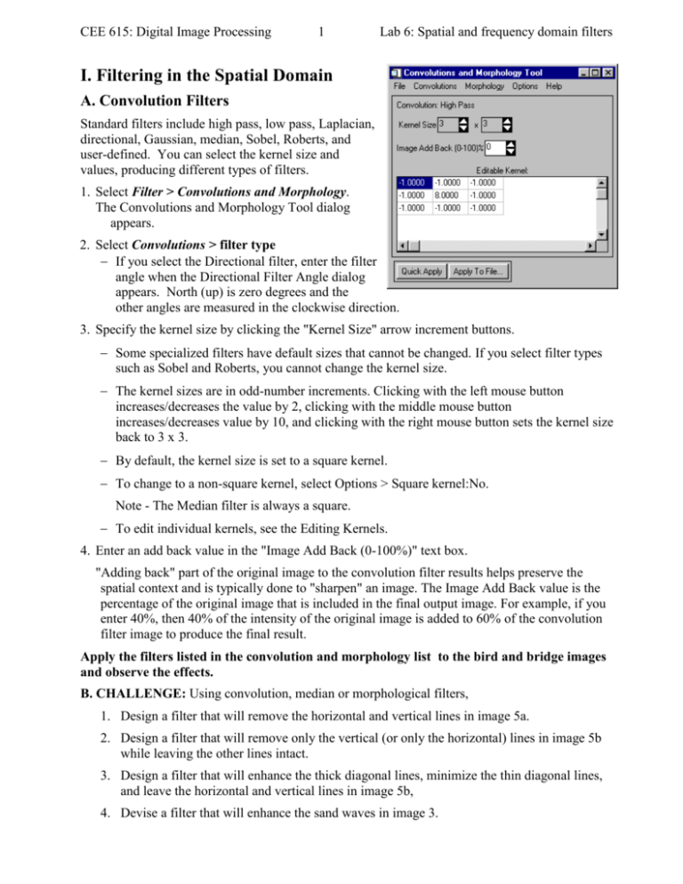
CEE 615: Digital Image Processing 1 Lab 6: Spatial and frequency domain filters I. Filtering in the Spatial Domain A. Convolution Filters Standard filters include high pass, low pass, Laplacian, directional, Gaussian, median, Sobel, Roberts, and user-defined. You can select the kernel size and values, producing different types of filters. 1. Select Filter > Convolutions and Morphology. The Convolutions and Morphology Tool dialog appears. 2. Select Convolutions > filter type If you select the Directional filter, enter the filter angle when the Directional Filter Angle dialog appears. North (up) is zero degrees and the other angles are measured in the clockwise direction. 3. Specify the kernel size by clicking the "Kernel Size" arrow increment buttons. Some specialized filters have default sizes that cannot be changed. If you select filter types such as Sobel and Roberts, you cannot change the kernel size. The kernel sizes are in odd-number increments. Clicking with the left mouse button increases/decreases the value by 2, clicking with the middle mouse button increases/decreases value by 10, and clicking with the right mouse button sets the kernel size back to 3 x 3. By default, the kernel size is set to a square kernel. To change to a non-square kernel, select Options > Square kernel:No. Note - The Median filter is always a square. To edit individual kernels, see the Editing Kernels. 4. Enter an add back value in the "Image Add Back (0-100%)" text box. "Adding back" part of the original image to the convolution filter results helps preserve the spatial context and is typically done to "sharpen" an image. The Image Add Back value is the percentage of the original image that is included in the final output image. For example, if you enter 40%, then 40% of the intensity of the original image is added to 60% of the convolution filter image to produce the final result. Apply the filters listed in the convolution and morphology list to the bird and bridge images and observe the effects. B. CHALLENGE: Using convolution, median or morphological filters, 1. Design a filter that will remove the horizontal and vertical lines in image 5a. 2. Design a filter that will remove only the vertical (or only the horizontal) lines in image 5b while leaving the other lines intact. 3. Design a filter that will enhance the thick diagonal lines, minimize the thin diagonal lines, and leave the horizontal and vertical lines in image 5b, 4. Devise a filter that will enhance the sand waves in image 3. CEE 615: Digital Image Processing 2 Lab 6: Spatial and frequency domain filters High Pass Filters High pass filters remove the low frequency components of an image while retaining the high frequency (local variations). They can be used to enhance edges between different regions as well as to "sharpen" an image. This is accomplished using a kernel with a high central value, typically surrounded by negative weights. ENVI's default high pass filter uses a 3 x 3 kernel with a value of "8" for the center pixel and values of "-1" for the exterior pixels. High pass filters can only have odd kernel dimensions. Low Pass Filters Low pass filtering preserves the low frequency components of an image, which smooths it. ENVI's default low pass filter contains the same weights in each kernel element, replacing the center pixel value with an average of the surrounding values. The default kernel size is 3 x 3. Laplacian Filters A Laplacian filter is a second derivative edge enhancement filter that operates without regard to edge direction. Laplacian filtering emphasizes maximum values within the image by using a kernel with a high central value typically surrounded by negative weights in the north-south and east-west directions and zero values at the kernel corners. ENVI's default Laplacian filter uses a 3 x 3 kernel with a value of "4" for the center pixel and values of "-1" for the north-south and east-west pixels. All Laplacian filters must have odd kernel sizes. Directional Filters A directional filter is a first derivative edge enhancement filter that selectively enhances image features having specific direction components (gradients). The sum of the directional filter kernel elements is zero. The result is that areas with uniform pixel values are zeroed in the output image, while those that are variable are presented as bright edges. Gaussian Filters A Gaussian filter passes a Gaussian convolution function of specified size over the image. The default is a 3 x 3 kernel and kernel dimensions must be odd. Median Filters Median filtering smooths an image, while preserving edges larger than the kernel dimensions (good for removing salt and pepper noise or speckle). ENVI's Median filter replaces each center pixel with the median value (not to be confused with the average) within the neighborhood specified by the filter size. The default is a 3 x 3 kernel. Sobel Filters The Sobel filter is a non-linear edge enhancement, special case filter that uses an approximation of the true Sobel function, and is a preset 3 x 3, non-linear edge enhancement operator. The size of the filter cannot be changed and no kernel editing is possible. Roberts Filters The Roberts filter is a non-linear edge detector filter similar to the Sobel. It is a special case filter that uses a preset 2 x 2 approximation of the true Roberts function, a simple, twodimensional differencing method for edge-sharpening and isolation. The size of the filter cannot be changed and no kernel editing is possible. User-Defined Convolution Filters You can define custom convolution kernels (including rectangular rather than square filters) by selecting and editing a user kernel. CEE 615: Digital Image Processing 3 Lab 6: Spatial and frequency domain filters There are several images supplied for use with this exercise: 1. Bird image: This is one of the images that was used in lecture. It is problematic for two reasons. First, it has been compressed (jpeg) and it has already been edge-enhanced. (Look closely ant the leading edge of the wings.) There are some details that show up well in this image, but it is probably not the best for demonstrating the use of filters. 2. The bridge image: This image has also undergone jpeg compression, but there is no obvious evidence of edge-sharpening. Given the repeating vertical, horizontal and angled elements in the image, it is particularly useful for exploring the use of directional filters. 3. Ooid Shoals, Bahamas: This is a one-band image of a shallow region in the Bahamas that shows an area of sand and sea grass. (The darker areas are largely sea grass.) The presence of sand waves and the structure and texture of the sea grass make for interesting targets for filtering operations. There is also fairly obvious banding (vertical striping) in this image that will be sensitive to some of the spatial filters. 4. Ginna: This is a 3-band image of an area in Rochester, NY near the Ginna power station. Only the red channel is shown at right. Interesting features to observe when using the filters are the orchards vs. the wooded areas. Also note the effect of filters on the power plant (lower right) and on details in the water (bottom). 5. Test Images a. b.


