CH16 - Bama.ua.edu
CH 16 – Electric Potential
This chapter covers electric potential energy, electric potential, and electrical capacitance.
Work done by an electric field
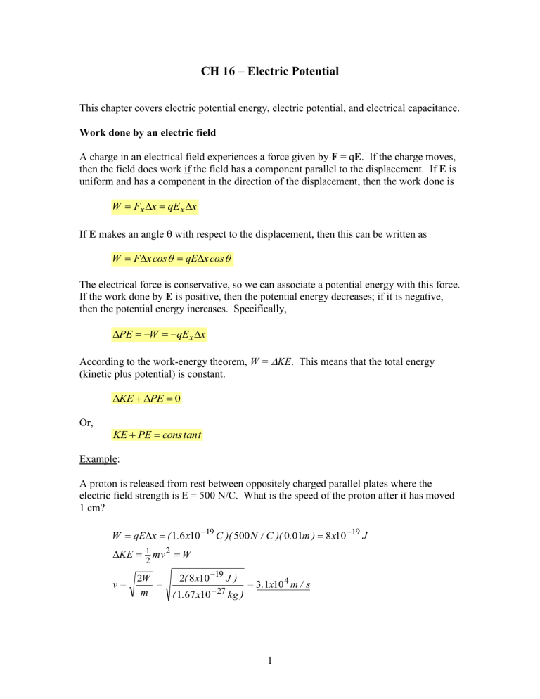
A charge in an electrical field experiences a force given by F = q E . If the charge moves, then the field does work if the field has a component parallel to the displacement. If E is uniform and has a component in the direction of the displacement, then the work done is
W
F x
x
qE x
x
If E makes an angle
with respect to the displacement, then this can be written as
W
F
x cos
qE
x cos
The electrical force is conservative, so we can associate a potential energy with this force.
If the work done by E is positive, then the potential energy decreases; if it is negative, then the potential energy increases. Specifically,
PE
W
qE x
x
According to the work-energy theorem, W =
KE . This means that the total energy
(kinetic plus potential) is constant.
KE
PE
0
Or,
KE
PE
Example:
cons tan t
A proton is released from rest between oppositely charged parallel plates where the electric field strength is E = 500 N/C. What is the speed of the proton after it has moved
1 cm?
W
qE
x
( 1 .
6 x 10
19
C )( 500 N / C )( 0 .
01 m )
8 x 10
19
J
KE
v
2 W m
1
2 mv
2
W
2 ( 8 x 10
19
( 1 .
67 x 10
27
J ) kg )
3 .
1 x 10
4 m / s
1
Electric Potential
The electric potential difference
V between two points A and B is defined as the electric potential energy difference of a charge q between these two points divided by the charge.
V
V
B
V
A
PE q
(unit = J/C =volt = V)
Since
PE
qE x
x (uniform E), then
V
E x
x
Electric potential is a way of characterizing the space around a charge distribution.
Knowing the potential, then we can determine the potential energy of any charge that is placed in that space. This is similar to the concept of electric field. The electric field is another way of characterizing the space around a charge distribution. If we know the field, then we can determine the force on any charge placed in that field. Electric potential is a scalar quantity (magnitude and sign (+ or -), while electric field is a vector
(magnitude and direction). Electric potential, just like potential energy, is always defined relative to a reference point (zero potential). The potential difference between two points,
V, is independent of the reference point.
Example:
A uniform field of magnitude E = 200 N/C is created by two oppositely charged parallel plates, as shown. What is the potential difference
V = V
C
– V
A
between points C and A? The distance from
A to B is 0.3 m and the distance from B to C is 4 m.
A
C
B
Solution:
V
CA
V
C
V
A
V
CB
V
BA
Since E is perpendicular to the displacement from B to C, then B and C are at the same potential. So,
V
CA
V
BA
E x
( x
B
x
A
)
( 200 N / C )( 0 .
3 m )
60 V
The negative sign means that point C is a lower potential than point A.
2
Example:
If the potential difference between the positive and negative plates were 1000 V and the separation of the plates were 10 cm, what would be the magnitude of the electric field between the plates?
Solution:
Since
V
E x
x , then
E x
(
1000 V
0 .
1 m
)
10 , 000 V / m (
10 , 000 N / C )
The positive sign means that E x
points to the right, in the direction of decreasing potential.
V
x
Potential Energy of Two Point Charges
The force between two point charges is F
k e q
1 q
2 r
2
. This force can do work by pushing the charges apart (if q
1
and q
2
have the same sign) or pulling them together (if q
1 and q
2
have opposite sign). There is a potential energy associated with these two charges.
The change in potential energy is the negative of the work done during the displacement.
Since the force is not constant, then we must calculate this work from the area under the force versus displacement curve, or by using integral calculus. Potential energy always depends on the choice of where the potential energy is assumed to be zero. For point charges, the convention is to assume that PE = 0 when r =
. The result is
PE
k e q
1 q
2
. r
Note that this equation is similar to the force formula except that PE varies inversely with r instead of r
2
. Also, PE is a scalar (it can be + or -), whereas force is a vector
(magnitude and direction).
Example:
Two protons are released from rest when they are 1 cm apart. What is their speed when they have moved very far apart?
3
Solution:
At r =
, PE = 0, so
PE
PE final
PE initial
k e e
2 r
KE
PE
.
1
2 mv
2 1
2 mv
2 v
k e e
2 mr
k e e
2
( both protons are r
( 9 x 10
9
)( 1 .
6 x 10
19
( 1 .
67 x 10
27
)( 0 .
01
)
)
2
3 .
7 moving m / s
)
Electric Potential of a Point Charge
Since
V
PE q
, then the potential of a single point charge is
V
k e q
, r where it is assumed that V = 0 when r =
.
Example:
What is the electric potential 50 cm from a point charge q = 1 x 10
-6
C?
Solution:
V
k e q r
( 9 x 10
9
)
1 x 10
6
0 .
5
1 .
8 x 10
4
V
18 kV
Example:
What is the electric potential at point P in the diagram to the right?
Solution:
5 m
4 m q
1
= 1.5 µC q
2
= -1 µC
V
V
1
V
2
( 9 x 10
9
2700 V
)
k e q
1 k e r
1
( 1 .
5 x 10
6
)
( 5 ) q
2 r
2
( 9 x 10
9
3000 V
300 V
)
(
1 x 10
6
( 3 )
)
P
3 m
4
Equipotential Surfaces
If a charge is moved perpendicular to an electric field, then no work is done and there is no change in potential energy and no change in electric potential. Thus, any surface over which the electric field is perpendicular is at constant potential and is called an
“equipotential” surface. For a point charge, equipotential surfaces would be spheres with the charge at the center. electric field lines equipotential surfaces
Equipotential surfaces for a positive/negative charge pair:
The surface of a charged conductor in equilibrium is an equipotential surface since the electric field is everywhere perpendicular to the surface. Also, the volume of a conductor is at constant potential. This is true since
V = -E x
x and since E = 0 everywhere inside a conductor.
Capacitance
A capacitor consists of two metal electrodes which can be given equal and opposite charges. If the electrodes have charges Q and –Q, then there is an electric field between them which originates on Q and terminates on –Q. There is also a potential difference between the electrodes which is proportional to Q. The capacitance of the configuration is defined as
C
Q
V
(unit = C/V = farad = F)
5
The capacitance is a measure of the capacity of the electrodes to hold charge for a given potential difference.
A geometrical simple capacitor would consist of two parallel metal plates. If the separation of the plates is small compared with the plate dimensions, then the electric field between the plates is nearly uniform.
At the end of chapter 15 we saw that the electric field between two oppositely charged plates is given by E =
/
0
, where
is the charge per unit area (
= Q/A) on the plates.
Also, the potential difference between the plates is
V = Ed, where d is the separation of the plates. Thus, the capacitance is
C
Q
V
A
Ed
0
EA
,
Ed
Or
C
0
A
(parallel plate capacitor) d
Example:
A capacitor consists of two plates 10 cm x 10 cm with a separation of 1 mm. What is the capacitance? If the capacitor is charged to a potential difference of 100 V, how much charge is on the capacitor?
Solution:
C
0
A d
Q
C
V
( 8 .
85 x 10
12
C
2
/ N
( 0 .
001 m ) m
2
)( 0 .
1 m )
2
( 8 .
85 x 10
11
F )( 100 V )
8 .
85 x 10
9
C
8 .
85 x 10
11
F
(
8 .
85 nC )
(
88 .
5 pF )
6
Combinations of Capacitors
Circuits can have multiple capacitors. In the simplest configurations, the capacitors would be either in parallel, in series, or in a combination of series and parallel.
Capacitors in parallel
In the parallel circuit, the electrical potential across the capacitors is the same and is the same as that of the potential source (battery or power supply). This is because the capacitors and potential source are all connected by conducting wires which are assumed to have no electrical resistance (thus no potential drop along the wires). The two capacitors in parallel can be replaced with a single equivalent capacitor. The charge on the equivalent capacitor is the sum of the charges on C
1
and C
2
. (This is the meaning of equivalent.) Thus,
Q
C
||
Q
1
V
Q
2
C
1
V
1
C
2
V
2
Since
V =
V
1
=
V
2
, then
C
||
C
1
C
2
V
Capacitors in series
C
1
Q
1
C
2
Q
2
V
C
||
Q
In the series circuit, the potential of the source is the sum of the potentials across C
1
and
C
2
. This is a consequence of conservation of energy. (A test charge moved across the source must have the same change in potential energy as a test charge moved across C
1 and then across C
2
.) The charges on each capacitor are the same (since each charge comes from the potential source). Also, the charge on each capacitor is the same as the charge on the single equivalent capacitor, C series
. Thus,
V
V
1
V
2
Q
C s
Q
C
1
1
Q
2
C
2
Or, since Q = Q
1
= Q
2
,
7
1
1
C
1
1
C
2
C s
Another way of writing this equation is
C s
C
C
1
1
C
2
C
2
V
C
C
1
2
Q
1
V
1
Q
2
V
2
V
C s
Q
For more than two capacitors in parallel or in series, the addition equations are
C
||
C
1
C
2
C
3
.
.
.
1
C s
1
C
1
1
C
2
1
C
3
.
.
.
Energy Stored in a Capacitor
The energy stored in a charged capacitor is given by
U
1
2
Q
V , where Q is the charge on the capacitor and ∆V is the voltage (potential) across the capacitor. If we moved a small charge q through a potential difference ∆V, the change in potential energy would be U = q∆V. The reason for the factor of ½ in the above equation is because the potential varies from 0 to ∆V as the capacitor is charged, so we must take the average to find the total work done in charging it.
Using Q = C∆V, we can alternatively write the energy stored as
U
1
2
C (
V )
2 1
2
Q
2
C
8
Example:
A 3-µF and a 6-µF capacitor are connected in parallel to a 12-V battery. Find the charge on each capacitor, the equivalent parallel capacitance, and the total energy stored.
Solution:
Q
1
C
1
V
( 3
F )( 12 V )
36
C
36 x 10
6
C
Q
2
72 x 10
6
C
C
||
C
C
1
2
V
C
2
( 6
F
3
F
)( 12 V
6
F
)
72
C
9
F
U
1
2
C
||
(
V )
2 1
2
( 9 x 10
6
F )( 12 V )
2
6 .
48 x 10
4
J
648
J
Example:
The capacitors in the above example are now connected in series to the 12-V battery.
Find the charge on each capacitor, the voltage across each capacitor, the equivalent parallel capacitance, and the total energy stored.
Solution:
The equivalent capacitance and the charge on the equivalent capacitance are
C s
Q s
C
C
1
1
C
2
C
C s
V
2
( 3 )( 6 )
3
6
( 2
F
)( 12 V
2
F
)
24
C
We note that for series capacitors, Q
1
= Q
2
= Q s
. So, the voltages across the capacitors are
V
1
V
2
Q
1
C
1
Q
2
C
2
24
C
3
F
24
C
6
F
8 V
4 V
Note that the smaller voltage is across the larger capacitor and vice-versa. Also, note that
V
1
V
2
12 V , as is required.
The energy stored is
U
1
2
C s
(
V )
2 1
2
( 2
F )( 12 V )
2
144
J
9
Example:
In the circuit below, find the total equivalent capacitance, the charge on each capacitor, and the voltage across each capacitor.
C
1
=
3 µF
V =
24 V
C
2
=
2µF
C
3
=
4 µF
Solution:
We will not give the complete solution here, but you should learn how to work it.
Suggestion: Find the parallel equivalent of C
2
and C
3
. This reduces the circuit to two capacitors in series. Then solve this using the previous example.
10


![Sample_hold[1]](http://s2.studylib.net/store/data/005360237_1-66a09447be9ffd6ace4f3f67c2fef5c7-300x300.png)


