1 - staff.city.ac.uk
Tutorial 10 – Series and Parallel AC Circuits
TUTORIAL 10
SERIES AND PARALLEL AC CIRCUITS
1.
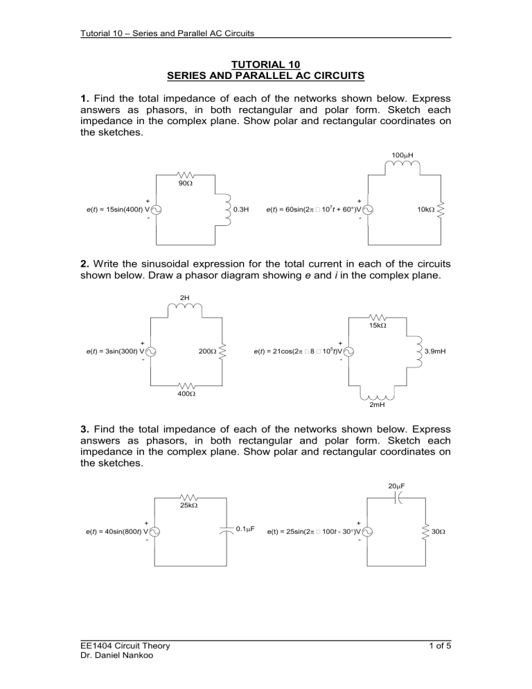
Find the total impedance of each of the networks shown below. Express answers as phasors, in both rectangular and polar form. Sketch each impedance in the complex plane. Show polar and rectangular coordinates on the sketches.
100 m
H
90
W
+ e ( t ) = 15sin(400 t ) V
-
0.3H
+ e ( t ) = 60sin(2 p ´
10
7 t + 60
°)V
-
10k
W
2.
Write the sinusoidal expression for the total current in each of the circuits shown below. Draw a phasor diagram showing e and i in the complex plane.
2H
15k
W
+ e ( t ) = 3sin(300 t ) V
-
200
W
+ e ( t ) = 21cos(2 p ´
8
´
10
5 t )V
-
3.9mH
400
W
2mH
3.
Find the total impedance of each of the networks shown below. Express answers as phasors, in both rectangular and polar form. Sketch each impedance in the complex plane. Show polar and rectangular coordinates on the sketches.
20 m
F
25k
W
+ e ( t ) = 40sin(800 t ) V
-
0.1
m
F
+ e(t) = 25sin(2 p ´
100 t - 30
°
)V
-
30
W
EE1404 Circuit Theory
Dr. Daniel Nankoo
1 of 5
Tutorial 10 – Series and Parallel AC Circuits
4.
Write the sinusoidal expression for the total current in each of the circuits shown below. Draw a phasor diagram showing e and i in the complex plane.
j 20
W
1k
W
+ e ( t ) = 10sin(10
5 t ) V
-
0.002
m
F
+ e(t) = -cos( w t + 45
°
)V
-
j 160
W
2k
W
5.
For the circuit shown below: i ↑
+ e = 20
´
0
°
V
-
20
W j 60
W
500
W
j 80
W a) Find the total impedance in polar form. Draw a phasor diagram showing all components of the impedance. b) Find the current i in polar form. c) Find the voltages v
R
, v
L
and v
C
across the resistor, inductor and capacitor respectively in polar form. d) Verify Kirchhoff’s voltage law around the circuit. e) Draw a phasor diagram showing e , i , v
R
, v
L
and v
C
in the complex plane.
6.
For the circuit shown below:
2.5
m
F i ↑
+ e ( t ) = 60sin(500 t + 60 °)V
-
300
W a) Find the total impedance Z
T
in polar form.
EE1404 Circuit Theory
Dr. Daniel Nankoo
2 H
2 of 5
Tutorial 10 – Series and Parallel AC Circuits b) Find the current i in polar and sinusoidal form. c) Find the voltage across each component in polar form. d) Draw a phasor diagram showing e , i , v
R
, v
L
and v
C
in the complex plane.
7.
Find the polar and rectangular forms of the admittance of a) a 40kΩ resistor b) a 5 m
F capacitor at 16kHz c) a 25mH inductor at 50
10 3 rad/s d) a 0.01
m
F capacitor at DC
8.
a) Find the total admittance of each of the circuits below: i
T
→
+ e = 40
´
0
°
V f = 300Hz
-
20 Ω j 20 Ω i
T
↑
+ e ( t ) = 15sin(4
´
10
3 t + 30 °)V
-
0.25
m
F 0.5H
1250 Ω b) Draw a phasor diagram showing each admittance in the complex plane.
Identify the conductance and susceptance components of each admittance on the diagram. c) Find the total impedance in polar and rectangular form.
EE1404 Circuit Theory
Dr. Daniel Nankoo
3 of 5
Tutorial 10 – Series and Parallel AC Circuits
9.
Find the total current i
T
in each of the circuits below in polar and sinusoidal form. Draw a phasor diagram showing e and i
T
in the complex plane. i
T
→
+ e ( t ) = 16cos(5000 t )V
-
C
1
=
2 m
F
L =
0.04H
R =
50
Ω
C
2
=
1 m
F j 9k Ω i
T
↑
+ e = 25
´
-60
°
V f = 10kHz
-
j 9k
Ω
10k Ω
10.
Find the total current i
T
in the circuit shown below. Then use the current divider rule to find the currents i
1
and i
2
. Express each current in polar form.
Check your answers by finding i
1
and i
2
directly, and then adding to find i
T
.
↑ i
T
↓ i
1
↓ i
2
+ e = 100
´
0 ° V
-
Z
1
=
40 – j 60 Ω
Z
2
=
60
´
30 °Ω
EE1404 Circuit Theory
Dr. Daniel Nankoo
4 of 5
Tutorial 10 – Series and Parallel AC Circuits
11.
For the circuit shown below:
+ e = 30
´
0 ° V
-
300 Ω j 500 Ω a) Find the power factor. b) Use the power factor to find the average power dissipated by the circuit. c) Verify that the power computed in part (b) is the same as the power dissipated by the resistor.
EE1404 Circuit Theory
Dr. Daniel Nankoo
5 of 5
