Supplemental_Material
advertisement

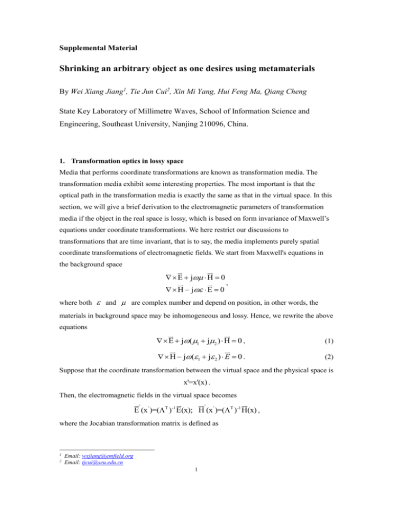
Supplemental Material Shrinking an arbitrary object as one desires using metamaterials By Wei Xiang Jiang1, Tie Jun Cui2, Xin Mi Yang, Hui Feng Ma, Qiang Cheng State Key Laboratory of Millimetre Waves, School of Information Science and Engineering, Southeast University, Nanjing 210096, China. 1. Transformation optics in lossy space Media that performs coordinate transformations are known as transformation media. The transformation media exhibit some interesting properties. The most important is that the optical path in the transformation media is exactly the same as that in the virtual space. In this section, we will give a brief derivation to the electromagnetic parameters of transformation media if the object in the real space is lossy, which is based on form invariance of Maxwell’s equations under coordinate transformations. We here restrict our discussions to transformations that are time invariant, that is to say, the media implements purely spatial coordinate transformations of electromagnetic fields. We start from Maxwell's equations in the background space E j H 0 H j E 0 , where both and are complex number and depend on position, in other words, the materials in background space may be inhomogeneous and lossy. Hence, we rewrite the above equations E j(1 j2 ) H 0 , (1) H j(1 j 2 ) E 0 . (2) Suppose that the coordinate transformation between the virtual space and the physical space is x'=x'(x) . Then, the electromagnetic fields in the virtual space becomes ' ' E (x ' )=( T )-1 E(x); H (x ' )=( T )-1 H(x) , where the Jocabian transformation matrix is defined as 1 2 Email: wxjiang@emfield.org Email: tjcui@seu.edu.cn 1 xk' x ; [ 1 ]ij i' . ki xi x j By the tensor analysis, we know the following identity ' ' E ' ( E) ( H) , ' H , det() det() which was also proved in Ref. [1,2,3]. To make the form of Maxwell’s equations invariable under spatial transformations, the permittivity and permeability in the virtual space have to be ' =1' +j2' 1 T 2 T , j det() det() ' =1' +j 2' 1 T 2 T . j det() det() Hence, if the material in original space is lossy, the transformed material will be lossy, furthermore, the loss will be anisotropic. 2. The effective material parameters and test system of the shrinking device For the experimental verification, we measured the electric-field distributions of the shrinking device in a parallel-plate waveguide field-mapping system (see Fig. S1c). A similar test system has been described and discussed previously [4]. The distance between two flat aluminium plates is set as 13 mm, and the shrinking device is placed on the centre of the lower plate, which is mounted on a step motor which can translate in two dimensions. As excitations, either a monopole probe is fixed inside the planar waveguide as the feeding source, or a finite-width plane wave is introduced using a coaxial-to-waveguide transition attached to the lower plate. A detection probe is embedded on the top plate to measure the electric fields on a plane above the shrinking shell under test, which can scan in a region of 192×192 mm2. The source and detection probe are connected to two ports of a vector network analyzer (Agilent PNA-LN5230C) via cables. Then the measured data are sent to the controlling computer for post-processing. 2 Figure S1. (a) The refractive index distribution for the designed shrinking device. (b) The effective permittivity ( z ) and permeability ( r ) of the metamaterial unit cells with varying h1 at designed frequency. (c) The experiment system for the fabricated shrinking device. 3. The measurement results for square dielectric and metallic objects without shrinking devices Figure S2. (a) The measurement result of the square dielectric object. (b) The measurement result of the square metallic (copper) object. 4. Full-wave simulation and measurement results for circular dielectric objects In order to validate our design furthermore, we provide simulation and measurement results of circular objects covered by the same shrinking device. The reduced material parameters of the illusion device are described in Eq. 4 in the main text. Fig. S3(a) shows the full-wave simulation result of electric fields inside and outside the virtual object, a dielectric cylinder with the permittivity 9 and unit permeability. The dimensions of the real and virtual objects and the shrinking shell are given by a=24 mm, b=48 mm, and c=8 mm. Here, we set 1 1 3 and 1 1 , i.e., the interspace of the shrinking shell is free space and the working frequency is 9.8 GHz. The illusion effect of the shrinking device with rescaled parameters is shown in Fig. S3(b). We clearly observe that the scattering patterns are very similar in Figs. S3(a) and S3(b). The measured electric-field distribution of the shrinking device is given in Fig. S3(c), which has good match to Fig. S3(b). Figure S3. (a) The electric-field distributions of an 8-mm-radius dielectric cylinder with the permittivity 9 and the unit permeability under the illumination of finite-width plane waves. (b)(c) The simulation and measurement results of the shrinking shell with rescaled parameters for the circular dielectric object under the illumination of plane waves. (b) Simulation result. (c) Measurement result. 5. Full-wave simulation and measurement results for circular metallic objects For a circular metallic object, the simulation and measurement results of the shrinking device are shown in Fig. S4, in which S4(a) and S4(b) demonstrate the simulated and measured electric fields for a bare circular metallic object with radius 24 mm, respectively, under the excitation of the monopole source. Obviously, the two results have excellent agreements, and a large shadow region is observed. When the metallic cylinder is covered by the shrinking device, the measured electric field shows a much smaller shadow region (see Fig. S4d), which matches to the measured electric field of a smaller metallic cylinder with radius 8 mm outside the shrinking device (see Fig. S4c). Hence, the illusion device shrinks the metallic cylinder as desired. 4 Figure S4. Full-wave simulation and measurement results of the electric fields for circular metallic objects under the excitation of a monopole source. (a) The simulation result of the bare metallic cylinder with the radius 24 mm. (b) The measurement result of the bare metallic cylinder with the radius 24 mm. (c) The measurement result of the bare metallic cylinder with the radius 8 mm. (d) The measurement result of the metallic cylinder with the radius 24 mm covered by the shrinking device. 5


