Experiment Title
advertisement
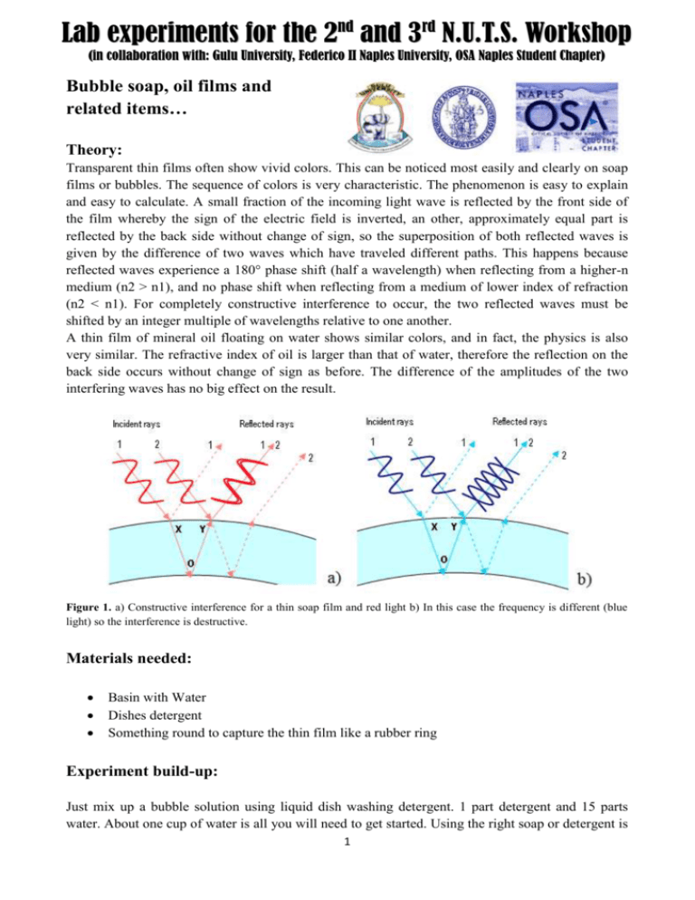
Lab experiments for the 2nd and 3rd N.U.T.S. Workshop (in collaboration with: Gulu University, Federico II Naples University, OSA Naples Student Chapter) Bubble soap, oil films and related items… Theory: Transparent thin films often show vivid colors. This can be noticed most easily and clearly on soap films or bubbles. The sequence of colors is very characteristic. The phenomenon is easy to explain and easy to calculate. A small fraction of the incoming light wave is reflected by the front side of the film whereby the sign of the electric field is inverted, an other, approximately equal part is reflected by the back side without change of sign, so the superposition of both reflected waves is given by the difference of two waves which have traveled different paths. This happens because reflected waves experience a 180° phase shift (half a wavelength) when reflecting from a higher-n medium (n2 > n1), and no phase shift when reflecting from a medium of lower index of refraction (n2 < n1). For completely constructive interference to occur, the two reflected waves must be shifted by an integer multiple of wavelengths relative to one another. A thin film of mineral oil floating on water shows similar colors, and in fact, the physics is also very similar. The refractive index of oil is larger than that of water, therefore the reflection on the back side occurs without change of sign as before. The difference of the amplitudes of the two interfering waves has no big effect on the result. Figure 1. a) Constructive interference for a thin soap film and red light b) In this case the frequency is different (blue light) so the interference is destructive. Materials needed: Basin with Water Dishes detergent Something round to capture the thin film like a rubber ring Experiment build-up: Just mix up a bubble solution using liquid dish washing detergent. 1 part detergent and 15 parts water. About one cup of water is all you will need to get started. Using the right soap or detergent is 1 important. A good choice is a liquid dish washing detergent that is exclusively for hand washing. You can add some glycerin if you have it. Wet the rubber ring or plastic frame into the solution and enjoy the beautiful colors. When the frame is vertical the solution is thinner at the top compared to the bottom, so we can see all the rainbow colors repeating from top to bottom. Figure 2. a) Tapered soap film in an inclined frame: reflecting light from the overcast sky. Due to gravity, the film is very thin on top; its thickness is increasing downwards. b) Oil drops spread to thin films on wet pavement. Conclusions: This experiment shows the so called thin-film interference effect which is one of the few interference effects that can be easily shown with non-coherent light. The double reflection of the incoming wave on the two air/liquid interfaces makes this effect possible because the thickness of the film is comparable to the wavelengths of visible light. 2 Lab experiments for the 2nd and 3rd N.U.T.S. Workshop (in collaboration with: Gulu University, Federico II Naples University, OSA Naples Student Chapter) CD Spectroscope Theory: A diffraction grating is a piece of material (usually plastic but some gratings do exist in nature) which has a very regular pattern inscribed on it. This inscription can consist of grooves on the surface or simply be a modulation of the materials index or refraction. By means of such an object it is possible to separate light in its components (different wavelengths) so it acts as a dispersive element. This is very useful in Spectrometry which is a spectroscopic technique used to asses the amount of a given chemical specie inside a material. The wavelengths of light reflected or emitted by a specific material are in fact strictly related to its chemical characteristics. The mathematical equation that relates the angle at which a normal incident beam of wavelength λ is reflected (or transmitted for transparent gratins) with the diffraction grating pattern spacing is called the Grating equation and is the following: dsin(θm)=m λ Where d is the grating spacing, m is an integer number, λ is the wavelength and θm is the diffraction angle. Why a compact disk (CD) behaves like a diffraction grating? On CDs data are stored in “pits” or as localized modulations of the refractive index. Usually on a CD each pit is 100 nm deep and 500 nm wide while the distance between the tracks is 1.6 μm (see Figure 1). The CD tracks are the pattern that creates the grating effect. Materials needed: - An empty cereal box or laundry detergent box A broken CD Duct tape Cutter 3 Figure 1. On CD ROMs data is stored inscribing pits on the surface. The distance or pitch between tracks is approximately 1.6 μm. Experiment build-up: Cut a slit on one side of the box it has to be a couple of cm long and very narrow. On the other side of the box make another cut to insert the CD the same way as Fig. 2 shows and an opening to look at the CD surface. This cut has to be at 60° cause this is the angle at which the center wavelength of the visible spectrum (green light) is reflected. Put the CD into place and fix it firmly with the duct tape. Point the slit towards a light source and look inside the opening, you should see a nice light spectrum reflected on the CD top surface. If the spectrum is too dim you should make the slit a little wider, while if the spectrum is too blurry the slit should be narrower. Figure 2. The CD Spectroscope. Conclusions: Different light sources and in general light reflected or emitted by different materials has a different spectrum. By means of a spectroscope one can see what are the wavelength components of this light, in this case just in the visible spectrum. More in general a Spectrometer is capable of discriminating the various wavelength components of the light received and also evaluate their relative intensity. 4 It is very interesting to compare different sources of light in terms of their spectrum. The light coming from the sun or from an incandescent bulb has an uniform spectrum while that emitted from a neon bulb or from a laptop PC screen shows many lines. Sub-experiment: try to use a fixed wavelength light source like that of a red laser (600 nm approximately) to evaluate the pitch of the CD ROM tracks, making use of the Grating Equation. Suggestion: it is better to show the effect in transmission so take off the CD reflective coating with the help of some scotch tape. Shine the laser from one side of the grating and look at the pattern created on a screen at a fixed distance. You should notice some spots regularly separated from a central one. The ratio of the distance between the central and first side spot and the between the screen and the grating is the tangent of the diffraction angle θm. 5 Lab experiments for the 2nd and 3rd N.U.T.S. Workshop (in collaboration with: Gulu University, Federico II Naples University, OSA Naples Student Chapter) Dispersion and Prisms Theory: When a material exhibits different refractive indexes for different frequencies of the light passing through it this material is called dispersive. Prisms are object made of such dispersive materials that can be used to separate light into its constituent spectral colors. Figure 1. A Prism The most known effect of dispersion is rainbow. The water droplets which are very abundant in the air after the rain act singularly as small prisms separating the spectral colors of the light coming from the sun and create this amazing effect. Even a water glass can act as a prism as this simple experiment will show Materials needed: A water glass A dark room A torch light A flat white surface (screen) Experiment build-up: Shine the light of the torch through the water glass an look at what happens on the screen. On the borders of the central area where light is more intense you should notice the light separating in its different color components from red to blue. Conclusions: White light is made up of many waves which differ in frequency and wavelength and propagate through dispersive media at speeds. This effect which is the reason why we can see raibows in the sky after the rain, can be exploited to separate light in its constituent spectral colors. 6 Lab experiments for the 2nd and 3rd N.U.T.S. Workshop (in collaboration with: Gulu University, Federico II Naples University, OSA Naples Student Chapter) Double Slit Interference Theory Thomas Young first demonstrated the interference of light in 1801. His experiment gave strong support to the wave theory of light. In the following experiment we will show interference fringes created when a coherent1 light source (in this case a laser pointer) passes through a double slits. Laser light produces an intense beam of monochromatic (single frequency) light. All the waves across the beam are in phase. The beam illuminates the slits, which are narrow to ensure adequate diffraction2. Figure 1. Double slit interference construction. The diffracted beams from the two slits will overlap producing interference. The interference pattern due to the superposition of the waves appears on the screen as alternate dark and bright bands, called fringes. The bright fringes are caused by constructive interference and the dark fringes by destructive interference. The interference is observable since each slit acts as a coherent source of light as it is derived from a single source. This is understandable because of the Huygens’s principle, the idea that each point on a wave can be considered to be a source of secondary waves. Applying this to the two slits, each slit acts as a source of light of the same wavelength, with the light from the two slits interfering constructively or destructively to produce an interference pattern of bright and dark lines. Bright fringes occur at points of constructive interference. This happens when the path difference between the waves is nλ (where n = 0, 1, 2...). Dark fringes occur at points 1 Two sources of light are said to be coherent if the waves emitted from them have the same frequency and are 'phase-linked'; that is, they have a zero or constant phase difference. 2 When wavefronts pass through a narrow slit they spread out. This effect is called diffraction. The amount of diffraction depends upon the size of the slit. If the slit is comparable in size to the wavelength of the wave then maximum diffraction occurs. 7 of destructive interference; this happens when the path difference is nλ/2 (where n = 0, 1, 2...). From figure 1, for the first bright fringe, the path difference is given by the distance s1Z. Using trigonometry, we can show that: path difference W sin tan and s s s For small values of θ, sinθ ≈ tanθ, so: W Ws and then: s D D Materials needed: - Microscope glass slides Aluminum foil A sharp cutter A laser pointer Some holder can help A ruler Experiment build-up: The double slit can be made for example with a microscope slide covered with aluminum tape on which two notches are made with the help of a sharp cutter. We can place the double slit on a table (using some holder if you have). Using the laser pointer directly in front of it, we should be able to observe an interference path on the screen consisting of equally and narrowly spaced fringes with a superimposed pattern of periodic intensity variation. Figure 2. Double slit experiment. Using the ruler we can measure the distance W between the first two fringe from the screen. At the same way we can measure the distance D between screen and slits. If the value of s (distance between slits) is known it is possible to determine the laser pointer wavelength λ. Or, if we know λ we can obtain s. 8 Conclusions: Using a very simple experimental setup we are able to observe a physical phenomena which shows the wave nature of the light. At the same time we can measure the wavelength of a laser source using simply a ruler. 9 Lab experiments for the 2nd and 3rd N.U.T.S. Workshop (in collaboration with: Gulu University, Federico II Naples University, OSA Naples Student Chapter) Interference with a mirror Theory: Two beam interference fringes are one of the more instructive topic in physical optics. A simple way to obtain two identical sources was conceived by Lloyd 3 using a mirror M. Constructive interference occurs when the phase difference δ between the electromagnetic waves from S and S’ to a point P in the plane of observation is 2nπ where n is an integer. Figure 1. Interference with a mirror In Lloyd’s experiment an additional phase change of π occurs upon reflection at the air/glass boundary. If λ is the wavelength of the light, the phase difference between the waves from S and S’ will be: (S 2 P SP ) (1) At the point P there is a superposition of waves of the same frequency differing in phase by δ giving an electric field of amplitude: E ( P ) E cos t cos( t ) 2 E cos t / t cos( / t ) 0 0 The time-averaged intensity at P is proportional to the average of the square of the electric field: 2 2 I( P ) 2 E /2which has a maximum when 2n . 0cos It can be demonstrated that the separation x of successive interference fringes in the plane of observation is given by x D/d. 3 Lloyd's mirror is a classic optics experiment and was first described in 1834 and again in 1837 by Humphry Lloyd in the proceedings of the Royal Irish Academy of Science 10 Materials needed: Mirror Laser pointer Screen Ruler Experiment build-up: Placing the mirror on a table (or some equivalent place) we can shine the laser pointer light on the mirror as depicted in Figure 1. Observing the interference path at the screen we should be able to measure the fringe separation an so the light source wavelength. Conclusions: Using a very simple experimental setup we are able to observe a physical phenomenon which shows the wave nature of the light. At the same time we can measure the wavelength of a laser source using simply a ruler. 11 Lab experiments for the 2nd and 3rd N.U.T.S. Workshop (in collaboration with: Gulu University, Federico II Naples University, OSA Naples Student Chapter) Lenses with water Theory A lens is an optical device, which transmits and refracts light, converging or diverging the beam. Essentially, lens is a transparent object (usually made by glass or transparent plastic) confined by two non-planar refracting surfaces. Lenses with axial symmetry are - Spherical – the surfaces are parts of surfaces of spheres Aspheric – the surfaces have more complex shape Other type of lenses is cylindrical lenses, that don’t have axial symmetry and their surfaces are parts of side surfaces of a cylinder. Such lenses converge the beam into the thin line and not a dot, as spherical ones. Figure 1. Different types of spherical lenses: biconvex, plano-convex, positive meniscus, negative meniscus, planoconcave, biconcave. Points where the light beam, is concentrated after passing a converging lens, is called focal point and distances from lens center to its focal points are called focal lengths and are the main parameters of the lenses. Figure 2. Focal point F` and focal distance f` of a lens 1st Setup: Bottle lenses Materials needed: Transparent plastic bottles (used for water or drinks) Cutter or scissors Water Experiment build-up: 12 Clean the bottle from any sticker or glue Cut side parts of the bottles as shown on the example picture, so to have small containers with spherical, cylindrical or other bottom shapes Fill the containers with water and illuminate it from above with a flashlight or any other collimated light source to see the focusing effects Conclusions: The plastic parts are working as a container for the water, which by itself acts as a refracting medium. The shapes of lens are not limited to ones, demonstrated above, since there are a lot of different plastic bottles to cut. 2nd Setup: Water on glass lenses Materials needed: Microscope glass slides or any other thin transparent material slides Any paper with printed or written text on it (newspaper, journal, book etc.) A needle, or teaspoon, eye-dropper or any needle-shaped object (even the tip of the finger is ok, with some practice) Experiment build-up: Clean the microscope glass of any dust or dirt (if any) Using the needle, place a single drop on top of the glass Put the glass slide on top of the paper with printed text: the magnification should be visible by the eye Conclusions: The magnification by such plano-convex water lens may depend on the size of the droplet. Same experiments, involving the flashlight (as in the case of bottle lenses) can be done, if the glass slide is managed with care. 13 Lab experiments for the 2nd and 3rd N.U.T.S. Workshop (in collaboration with: Gulu University, Federico II Naples University, OSA Naples Student Chapter) Pinhole Viewer Theory: The image in the pinhole viewer is created on the basis of the rectilinear propagation of light. Each point on the surface of an illuminated object reflects rays of light in all directions. The hole lets through a certain number of these rays which continue on their course until they meet the projection plane where they produce a reverse image of the object. Figure 1. Pinhole geometry explains why the image is flipped on the screen Materials needed: An empty cereal box or laundry detergent box Waxed paper Black tape Scissors A pushpin or needle Experiment build-up: Cut a big flap in the front of the box by cutting across the middle down one side, and across the bottom. Cut a piece of waxed paper that is as wide as the bottom of the box but a few inches longer. Tape it inside the box as shown, about two inches from the bottom of the box. Using pushpin or needle, make a hole in the bottom of the box. Then close the flap and tape it back in place with black tape. Be sure to tape all around the flap so that no light can leak into the box except through the hole in the bottom. Cut off the flaps from the top of the box. Cut a slight curve along one edge where you removed the boxtop, so that the curve of the box more or less matches the curve of your forehead. 14 Figure 2. how to build a pinhole viewer from a cereal box Conclusions: Pinhole camera or camera obscura is one of the simplest optical imaging device in the shape of a closed box or chamber. In one of its sides is a small hole which, via the rectilinear propagation of light, creates an image of the outside space on the opposite side of the box. It will be also interesting to see what happens to the image when the pinhole diameter changes or when the distance between the object and the hole is changed. 15 Lab experiments for the 2nd and 3rd N.U.T.S. Workshop (in collaboration with: Gulu University, Federico II Naples University, OSA Naples Student Chapter) Mist on glass experiment: home made rainbow Theory: The rainbow is an optical phenomenon that appears when the Sun shines onto water droplets (clouds, mist, etc.) in the air and the light is decomposed into spectrum. This decomposition can be seen because water droplets act as small prisms on the light beam. When the light enters and exits the droplet, refraction occurs and the angle of refraction slightly depends on the wavelength (color) of the light. This way after the prism (or water droplet) the directions of the light beam depends on its wavelength and the white beam is decomposed into spectra. Figure 1. A prism, a water droplet and a schematic illustration of light decomposition inside them. The angle between incoming and outcoming beams in the water droplet case is around 40-42°. Materials needed: Clean microscopic glass slide or spectacles Light source (strong) Experiment build-up: The rainbow-like phenomena can be easily shown with just a glass slide. For doing it, one must simply breathe on in so it gets misted and immediately (before the mist evaporates) look through it at a strong light source. More trials may be necessary for finding the best slide inclination angle. Better picture can be made using spectacles instead of the glass slides. Conclusions: The simple trick of breathing on a glass and looking through it demonstrates the same rainbow that can be seen in the sky. The rainbow is an illustration of how one of the most noted optical effects – refraction works, decomposing the white light into multicolored beams. 16 Lab experiments for the 2nd and 3rd N.U.T.S. Workshop (in collaboration with: Gulu University, Federico II Naples University, OSA Naples Student Chapter) Scattering of light Theory: Why is the sky blue? Why are sunsets red? Although we don't realize it, scattering of light is very important for our daily life. Almost all objects scatter light, that means they reflect the light that illuminates them in all directions. If the objects around us would reflect light perfectly without scattering - like polished metal - it would be like in a mirror cabinet. There are several ways how scattering occurs, we pick two important examples: Random reflection on a rough surface. (Figure 1 left) Reflection (or refraction or diffraction) on impurities in the volume. (Figure 1 right) This is the type of scattering which plays the major role in medical applications. In tissues the light is scattered at cells or their components. In milk it is scattered mostly at the tiny fat droplets. Figure 1. Two ways of light scattering Materials needed: - A laser pointer (1st experiment) and a black box with a white lamp (2nd experiment) A transparent glass or a basin Water Milk or soluble milk powder Something to dispense the milk White cardboard screen Our eyes or a digital camera. 1st Experiment build-up: Shine the laser light through the transparent basin filled with water. The light should pass freely, and a nice spot be visible on the screen. Add some drops of milk or mud into the water a repeat the 17 experiment. The more milk we add to the solution the less the ray of light is able to get to the screen. If the light is shone close to the solution surface scattering is clearly visible. Remember to shake the glass when you add the milk in the end the scattering is so high that the light cannot pass trough the glass. Figure 2. 1st experiment scattering in a water/milk solution 2nd Experiment build-up: 1. Fill a clear 2 L plastic bottle with water. 2. Turn the lights off, and shine a flash-light through the water. Look at the water from all sides of the bottle. Describe what you see. 3. Add a few drops of milk to the water, and shake the bottle to mix it up. 4. Repeat step 2. Describe any color changes. If you don’t see any, add more milk until you do. 5. Is the water-and-milk mixture like air particles in the atmosphere? Investigate what happens if the light from the open end of the light box is shone through a beaker of water. Let the light through the beaker fall on a white cardboard screen and observe the color of the light. What happens if small amounts of milk are added to the beaker of water and stirred gently. Are there any changes in the color of the light passing through the milk onto the screen as more milk is added to the water? At the same time, what do you notice about the color of the light as seen from the sides of the beaker of milk? What color light is most likely to be scattered to the side as the light from the Sun passes through the atmosphere? Suggest how this makes the sky appear blue. You tend to look towards the Sun to see a beautiful sunset. How does the milky water demonstration explain why sunsets are mostly red? Conclusions: The milk solution is full of microscopic particles (which makes it look milky). These particles scatter the light from the blue end of the spectrum to the side, whereas the light from the red end of the spectrum passes through the milk solution. The atmosphere is also full of particles, air molecules and dust particles….. 18 Lab experiments for the 2nd and 3rd N.U.T.S. Workshop (in collaboration with: Gulu University, Federico II Naples University, OSA Naples Student Chapter) Stress Induced Polarization Theory: Some crystalline substances, such as quartz and calcite, have two indices of refraction. Such crystals are birefringent ("doubly refracting"). When a ray of unpolarized light enters a birefringent crystal, it divides into two rays. These two rays have different speeds and are polarized at right angles to each other. These waves travel through the material at different speeds, which are determined by the light's colour. When stressed, plastic and glass can become birefringent Viewed between polarizing filters, this birefringence appears as coloured contours. Materials needed: Two polarizing filters A transparent fork or thin pieces of plastic. A glass plate Transparent tapes Experiment build-up: Hold the fork or plastic letter above the first filter and below the second filter. Induce stress by squeezing the tines of the fork together or deforming the latter. Notice the coloured stress pattern. The experiment can be repeated with using the glass plate instead of the fork with transparent cellotape of different thickness taped on it. Try rotating one of the polarizing filters. Some orientations will give more dramatic colour effects than others. Conclusions: The first polarizing filter limits the vibration of light waves to one plane, that is, it polarizes the light. The white light is made up of light of all colours. When the plastic or glass is stressed is becomes birefringent and changes the direction of polarization of the outgoing light waves depending on the colour (wavelength). The direction of polarization determines whether light of a certain colour can pass through the second polarizing filter. If the new direction of polarization lines up with the second filter, light of that colour passes through the filter and you see it. If the new direction of polarization does not line up with the second filter, light of that colour is blocked. By rotating the filter, you can let different colours pass through, and the colours you observe will change. 19 Lab experiments for the 2nd and 3rd N.U.T.S. Workshop (in collaboration with: Gulu University, Federico II Naples University, OSA Naples Student Chapter) Water waveguide Theory: When light crosses a boundary between materials with different refractive indexes, the light beam will be partially refracted at the boundary surface, and partially reflected. Refraction of the light beams is governed by Snell’s law,which states n1 sinθ1=n2 sinθ2 (1) where n1 and n2 are the refractive indexes of the first and second medium respectively, θ1 and θ2 are the angle of incidence and angle of refraction respectively as shown in the figure. Figure 1. Snell's law If the light beam is incident at the interface of a optically “denser” medium (n1 < n2), the refracted ray will bend towards the normal. On the other hand if the beam is incident at the interface of a rare medium (n1 < n2), then the beam will bend away from the normal. An interesting case of refraction can occur when light travels from a medium of larger to smaller index. The light ray can actually bend so much that it never goes beyond the boundary between the two media. This case of refraction is called total internal reflection (TIR). The angle of incidence for which the angle of refraction is 90° is known as the critical angle (θc). When the angle of incidence exceeds the critical angle there is no refracted ray, but only the totally internally reflected ray. Water waveguide works on the principle of total internal reflection. 20 Figure 2. Total Internal Reflection Materials needed: A transparent container for water (like a fish tank) Laser pointer Bucket A pointed object (i.e. a nail) or a small drill Experiment build-up: Make a hole on one side of the fish tank close to the bottom and block it using a cork. Place the container on a table near to the edge and fill it with water. Align the laser so that the light beam falls on the center of the hole. Remove the cork so the water will flow out and observe several internal reflections occurring inside the ‘fiber’ of water. Figure 3. The fishtank water waveguide Conclusions: This experiment demonstrates the total internal reflection happening between the water-air interface. It shows how light can be guided effectively. 21 Lab experiments for the 2nd and 3rd N.U.T.S. Workshop (in collaboration with: Gulu University, Federico II Naples University, OSA Naples Student Chapter) Wave nature of light Theory Light is an electromagnetic radiation that propagates as a wave. A wave is a disturbance that propagates through space and time, usually with transference of energy. Mathematically, the most basic wave is the sine wave (or harmonic wave or sinusoid), with an amplitude u described by the equation: u(x,t)=Acos(kx-ωt+φ) Where u is wave of the electric or magnetic field propagating along the x axis at instant t, A its amplitude, k is the wavenumber (spatial frequency), ω its angular frequency, and φ its phase. The wavenumber and angular frequency are related to the wavelength and the frequency by the following equations: ω=2πf k=2π/λ It can be demonstrated that such a wave propagates at a constant speed υ which is given by the product of of frequency and wavelength: λf= υ This speed for an electromagnetic wave propagating in free space is called c and was measured to be around 300.000 km/s Figure 1. A sinusoidal wave propagating in the x direction and oscillating along the y direction. Polarization: Given that a wave can propagate in a particular direction (i.e. the x axis as in Fig. 1) it can oscillate actually in any other direction. Figure 1 shows a wave oscillating in the y direction but the wave can oscillate in any direction on the plane orthogonal to the x axis. This characteristic of light is called polarization. Polarizing sheets are layers of materials that are able to completely block light oscillating along a particular direction. Materials needed: A 3 m rope or a “slinky” (walking spring toy. See OSA optics suitcase) Two people A narrow frame or two wooden sticks 22 Experiment build-up: 1st step: Two people have to hold the two ends of a rope. While one hold it firmly and steady the other has to force the oscillation moving the rope end up and down or left to right (two of the infinite possible “polarizations”). At this point it is possible to see the lobes of the wave (there should be just two at first) and the wavelength. If the oscillating frequency is increased moving the rope end faster, it is possible to see that the number of lobed increases or equivalently the wavelength is reduced. 2nd step: if while the rope is oscillating up and down, two wooden sticks are put across it and parallel to the floor the wave is blocked, but if the rope is made oscillate from left to right then it can propagate freely. Conclusions: The first step shows the simple propagation of a wave on a rope and explains how wavelength and frequency are strictly related. It also shows that the wave can oscillate in many directions or “polarizations”. The second step shows how polarizing sheets can actually block a certain polarization of the wave and let another pass freely. 23
