Spin/Beam Dynamics Systematic Errors Bill Morse – BNL
advertisement
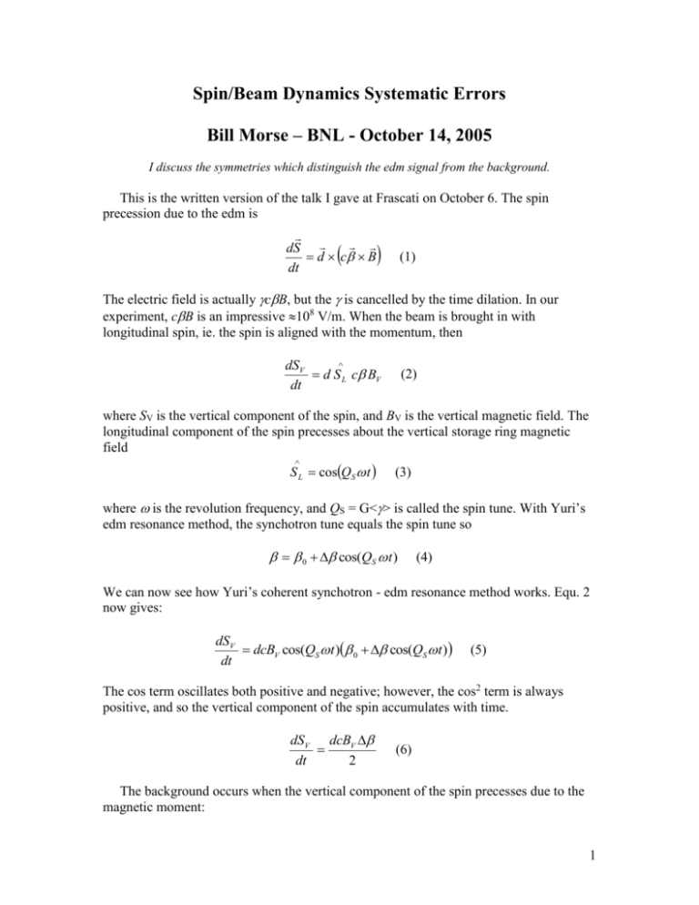
Spin/Beam Dynamics Systematic Errors Bill Morse – BNL - October 14, 2005 I discuss the symmetries which distinguish the edm signal from the background. This is the written version of the talk I gave at Frascati on October 6. The spin precession due to the edm is dS d c B dt (1) The electric field is actually cB, but the is cancelled by the time dilation. In our experiment, cB is an impressive 108 V/m. When the beam is brought in with longitudinal spin, ie. the spin is aligned with the momentum, then dSV d S L c BV dt (2) where SV is the vertical component of the spin, and BV is the vertical magnetic field. The longitudinal component of the spin precesses about the vertical storage ring magnetic field S L cosQS t (3) where is the revolution frequency, and QS = G<> is called the spin tune. With Yuri’s edm resonance method, the synchotron tune equals the spin tune so 0 cos(QS t ) (4) We can now see how Yuri’s coherent synchotron - edm resonance method works. Equ. 2 now gives: dSV dcBV cos(QS t ) 0 cos(QS t ) dt (5) The cos term oscillates both positive and negative; however, the cos2 term is always positive, and so the vertical component of the spin accumulates with time. dSV dcBV dt 2 (6) The background occurs when the vertical component of the spin precesses due to the magnetic moment: 1 dSV S L BR S R BL dt (7) where is the magnetic moment and S R sin QS t (8) At this point, you are probably saying “Bill, you are crazy: the neutron edm experiments have to worry about stray magnetic fields at the less than pico-Gauss level, while in our storage ring we have >Gauss radial magnetic fields”! However, we know that our storage ring will give a total, time-averaged vertical Lorentz force of zero, otherwise it is not a storage ring: FV 0 ec BR (9) If the radial magnetic field is not correlated with the velocity, then the average radial magnetic field is zero! This shows the power of this method: the focusing system makes the average radial magnetic field zero, unless it is correlated to the velocity. This radial magnetic field correlated to the velocity will be the main spin/beam dynamics systematic error (see below). For the longitudinal magnetic field we have Ampere’s law: B dl i (10) Integrating around the orbit, the average longitudinal magnetic field will be exactly zero, if we have no net current inside the orbit breaking the orbit plane. Before we go on to discuss the radial magnetic field correlated to the velocity background, we discuss a beautiful symmetry check we have in storage ring edm experiments. When injecting the longitudinally polarized beam clockwise (CW) vs. counter-clockwise (CCW): B B S L S L (11) Therefore, for the torque due to the edm: d c B d c B (12) The effect on the vertical component of the spin due to the edm changes sign CW vs. CCW. However, CW vs. CCW for the magnetic moment background gives: B B (13) 2 The torque due to the edm changes sign because the edm violates time reversal invariance (T), but the magnetic moment conserves T. Now, let’s suppose we have a run with the beam injected clockwise and we measure a spin precession as shown in Fig. 1. The total error (statistical plus systematic error) is shown, but we are going to argue that it will be dominated by the statistical error. However, we want to prove that what we have measured is actually due to T violation. Therefore, we have another run injecting the beam CCW (see Fig. 1). Thus we have shown that what we have measured is actually T violation. This is a unique and beautiful aspect of storage ring edm measurements. Fig. 1. Run 1 is for CW injection; run 2 is for CCW. S_V (a.u.) 5 0 0.5 1 1.5 2 2.5 -5 Run Next we discuss the dominant systematic error: the radial magnetic field that is correlated with the velocity. This could come, for example, from a skew quadrupole moment in a region with momentum dispersion. However, the effect on the vertical component of the spin depends on the strength of the vertical focusing. For a weak focusing machine: y(t ) Ymax cos(QV s / R V ) n QV2 R0 BR B0 y (14) (15) where QV is called the vertical betatron tune. If the vertical tune is much greater than the spin tune, then <FV> = 0 = e<BR> ec<><BR>, because the velocity oscillations are slow compared to the focusing system betatron oscillations. The functional dependence of this background [1] on the vertical and spin tunes is: 3 dSV 1 2 dt QV QS2 (16) Fig. 2. Vertical component of the spin after many turns (a.u.) vs. vertical betatron tune for the skew quadrupole weak focusing systematic error. 2 S_v/S (10^-3) 1 D 0 0 0.1 0.2 0.3 0.4 0.5 0.6 0.7 P 0.8 -1 -2 Q_v I did a spin tracking simulation for a continuous weak focusing machine with a skew quadrupole moment varying the vertical tune (see Fig. 2). A continuous weak focusing machine has momentum dispersion everywhere. This result for the vertical component of the spin after many turns agrees well with Yuri’s analytic calculation. The deuteron QS = 0.15, while the proton QS = 2.15 for this calculation. Let’s suppose that we run at two vertical tunes, for example, low-n: QV = 0.29, and high-n: QV = 0.56 (see Fig. 2). The ratio of equ. 16 for these two tune values R = 4.7. We now have two measurements of the polarimeter asymmetry corresponding to the vertical component of the spin for high-n and low-n : Ahi n Ad AhiSQ n (17) SQ SQ Alow n Ad Alow n Ad R Ahi n (18) where the asymmetry due to the edm, Ad, does not depend on the vertical tune, but the background asymmetry due to the skew quadrupole, ASQ, does. We can solve for the effect due the edm: A R Ad Ahin lown R ( R 1) (19) 4 For large R, the uncertainty is: Ad Ahin R Alown R Ahin 2 2 R (R 1) (20) We will measure the vertical and synchotron tunes accurately (Q 0.001) with Fourier analysis of the vertical and horizontal pickup electrode signals. In order to have a small uncertainty, we want Alow-n to be small and R to be large. If Alow-n is small, then Ahi-n is automatically small, since R is large. During E821 we took about 103 one hour runs. Let’s say after each one hour run, if Alow-n is statistically different from zero, then the operator will adjust a skew quadrupole correction magnet. Then we should have about half the runs with negative Alow-n and half with positive Alow-n. If the entire 103 hour data set does not have Alow-n < R2/ R times the statistical error, then the analyser can throw out a few of the positive, or negative runs until it is satisfied. Then we will be dominated by the high-n statistical error, Ahi-n. We plan alternate fills with low and high n, ie. we will change the quadrupole settings between fills. However, suppose the skew quadrupole term is not stable with time. Then the low-n and high-n fills will not sample the same skew quadrupole term. If this is a problem, then we will change the vertical tune during the fill with a fast quadrupole magnet (RFQ). If we power the RFQ with a simple sine wave at the revolution frequency, for example, then the ten bunches in the storage ring will have five different vertical tunes. The bunches will be separated by 210-8 s, and the polarimeter will keep track of which bunch is which. The dangerous perturbation BR = K ( - 0) comes from a skew quadrupole moment in a region with momentum dispersion, or a rotation of a dipole magnet. One could ask if the low and high n bunches sample slightly different transverse space inside the storage ring. However, this doesn’t matter, since these two cases are linear. Higher order nonlinear effects should be much smaller, but we haven’t investigated them yet. However, we sample these particles when they hit the polarimeter collimator or the slow extraction septum, for the inside/outside the ring polarimeter options respectively, so in fact they will sample very nearly the same transverse space in the storage ring. All this needs to be studied with tracking simulations. Also, for these vertical tunes the effect on the proton spin from the background changes very little (see Fig. 2), because these vertical tunes are much, much less than the proton spin tune of 2.15. This is an excellent check of the method. However, suppose the RFQ itself modifies K? It shouldn’t because it is a normal quadrupole in a region with zero momentum dispersion (D = 0). We can test this by changing D so that it isn’t zero and/or turning on a skew quadrupole winding in the RFQ. If we increase these by ten times the tolerance, for example, then we can see the effect in the asymmetry in about 1% of the running time, and correct it, ie. correct the D function and/or correct with the skew quadrupole winding. 5 Note that the general form of equs. 3 and 4 should have phases, which were dropped for simplicity in explaining the method. S L cosQS t L (21) 0 cos(QS t S ) (22) Both the edm effect, and the radial magnetic field correlated to velocity background, have a phase dependence: dSV cos( L S ) dt (23) Other systematic effects, for example, if the RF cavity is not centered vertically [2], have a different dependence, ie. sin(L - S), besides being dependent on the vertical tune. We plan to use this symmetry by varying the phase difference at injection. In conclusion, we believe that we have sufficient symmetry checks, ie. varying QV and (L - S), to keep the backgrounds below our statistical error. We check this by injecting clockwise and counter-clockwise, since the electric dipole moment violates T, but the magnetic moment doesn’t. References 1. Y. Orlov, EDM Note 69 (2004). 2. Y. Semertzidis, EDM Note 92 (2005). 6
