where the total angular momentum H is a (in the free
advertisement
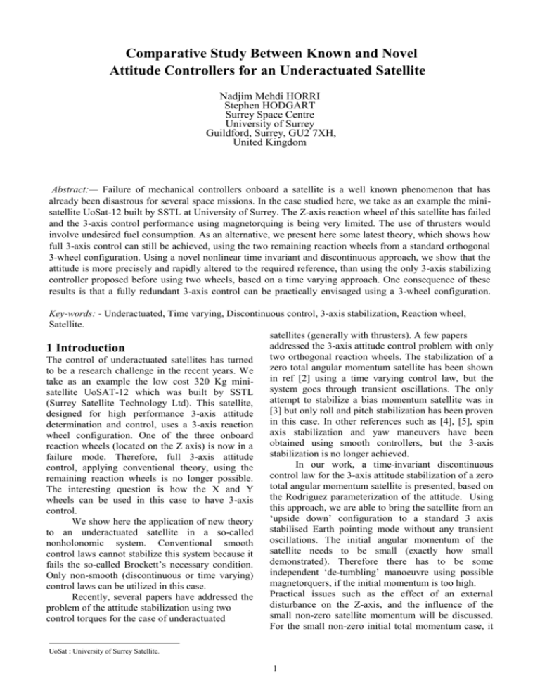
Comparative Study Between Known and Novel Attitude Controllers for an Underactuated Satellite1 Nadjim Mehdi HORRI Stephen HODGART Surrey Space Centre University of Surrey Guildford, Surrey, GU2 7XH, United Kingdom Abstract:— Failure of mechanical controllers onboard a satellite is a well known phenomenon that has already been disastrous for several space missions. In the case studied here, we take as an example the minisatellite UoSat-12 built by SSTL at University of Surrey. The Z-axis reaction wheel of this satellite has failed and the 3-axis control performance using magnetorquing is being very limited. The use of thrusters would involve undesired fuel consumption. As an alternative, we present here some latest theory, which shows how full 3-axis control can still be achieved, using the two remaining reaction wheels from a standard orthogonal 3-wheel configuration. Using a novel nonlinear time invariant and discontinuous approach, we show that the attitude is more precisely and rapidly altered to the required reference, than using the only 3-axis stabilizing controller proposed before using two wheels, based on a time varying approach. One consequence of these results is that a fully redundant 3-axis control can be practically envisaged using a 3-wheel configuration. Key-words: - Underactuated, Time varying, Discontinuous control, 3-axis stabilization, Reaction wheel, Satellite. satellites (generally with thrusters). A few papers addressed the 3-axis attitude control problem with only 1 Introduction two orthogonal reaction wheels. The stabilization of a The control of underactuated satellites has turned zero total angular momentum satellite has been shown to be a research challenge in the recent years. We in ref [2] using a time varying control law, but the take as an example the low cost 320 Kg minisystem goes through transient oscillations. The only satellite UoSAT-12 which was built by SSTL attempt to stabilize a bias momentum satellite was in (Surrey Satellite Technology Ltd). This satellite, [3] but only roll and pitch stabilization has been proven designed for high performance 3-axis attitude in this case. In other references such as [4], [5], spin determination and control, uses a 3-axis reaction axis stabilization and yaw maneuvers have been wheel configuration. One of the three onboard obtained using smooth controllers, but the 3-axis reaction wheels (located on the Z axis) is now in a stabilization is no longer achieved. failure mode. Therefore, full 3-axis attitude In our work, a time-invariant discontinuous control, applying conventional theory, using the control law for the 3-axis attitude stabilization of a zero remaining reaction wheels is no longer possible. total angular momentum satellite is presented, based on The interesting question is how the X and Y the Rodriguez parameterization of the attitude. Using wheels can be used in this case to have 3-axis this approach, we are able to bring the satellite from an control. ‘upside down’ configuration to a standard 3 axis We show here the application of new theory stabilised Earth pointing mode without any transient to an underactuated satellite in a so-called oscillations. The initial angular momentum of the nonholonomic system. Conventional smooth satellite needs to be small (exactly how small control laws cannot stabilize this system because it demonstrated). Therefore there has to be some fails the so-called Brockett’s necessary condition. independent ‘de-tumbling’ manoeuvre using possible Only non-smooth (discontinuous or time varying) magnetorquers, if the initial momentum is too high. control laws can be utilized in this case. Practical issues such as the effect of an external Recently, several papers have addressed the disturbance on the Z-axis, and the influence of the problem of the attitude stabilization using two small non-zero satellite momentum will be discussed. control torques for the case of underactuated For the small non-zero initial total momentum case, it UoSat : University of Surrey Satellite. 1 is also shown that we can bring the attitude to the desired reference with residual constant amplitude oscillations. In this paper , the objective is to present a novel two wheels 3-axis controller that improves the results of the only 3-axis stabilizing controller known to the author using two wheels (the time varying controller presented in ref [3]). where we define: Ni h i , i=1,3. Without any loss of generality, we assume one reaction wheel failure on the z-axis (which is precisely the case of UoSat-12). In this case, we have to set N 3 0, h3 0 , and the corresponding dynamic equation for the underactuated satellite is: I11 I 2 I 3 2 3 N1 3 h2 I 2 2 I 3 I1 31 N 2 3 h1 2 Problem Formulation (4) I 3 3 I1 I 2 1 2 1h2 2 h1 We have first to derive the satellite dynamic and kinematic models of the underactuated satellite. 2.3 Kinematic Model 2.1 Notations: A IB : Direction cosine matrix from inertial reference to body frame. I = I1 , I 2 , I 3 T : Inertia tensor of the body of the satellite about its centre of mass. P = p1, p2 , p3 T : Attitude of the satellite using Rodriguez parameters. ω = 1, 2 ,3 T : Vector of the angular velocity in body fixed reference frame. Iwi: Momentum of inertia of the ith wheel. i , zi : Rotation angle, and unit vector of the ith wheel rotational axis, respectively. h h1 , h2 , h3 : Angular momentum generated by the wheels in the body frame. H, L: Total angular momentum in the inertial and body frames respectively. Rodriguez parameters are used here for the representation of the attitude kinematics. These parameters are derived from the standard Euler axis/angle representation P [ p1, p2 , p3 ]T tan( / 2).e where e is the Euler axis and is the rotation about it. Alternatively each pi= qi/q4 where the q’s are the standard quaternions. The kinematic equation of a rigid body (satellite) using Rodriguez parameters is: p T 2.2 Dynamic Model If no external disturbance torque is assumed, we have: ωL 0 L (1) And the equation of the total angular momentum is: L Iω h 2 L A IB H Iω I wi ω i z i (6) 1 2 p 1 2 1 ( p 3 p1 p 2 ) 2 ( p 2 p1 p 3 ) 3 p1 1 1 2 p 2 2 ( p 3 p1 p 2 )1 ( p1 p 2 p 3 ) 3 p 2 2 2 1 2 p 3 2 3 ( p 2 p1 p 3 )1 ( p1 p 2 p 3 ) 2 p 3 3 (7) We first assume a zero total angular momentum satellite. We will show that in this case the kinematic model using Rodriguez parameters will be considerably simplified. The zero total angular momentum H = 0 condition can be written as: (2) Iω 2 I wi ω α i z i 0 (8) i1 By substituting L from equation (2), into the equation (1), we obtain the general Euler’s rotational equation using three reaction wheels: I 3 3 I1 I 2 1 2 N 3 1h2 2 h1 1 ~ pp T ω Ip 2 which can also be written for each component as : i 1 I11 I 2 I 3 2 3 N1 2 h3 3h2 I 2 2 I 3 I1 31 N 2 3h1 1h3 (5) which is equivalent to: ω 1x1 2 x 2 1z1 2 z 2 (9) (3) I wi z i (I I w1 I w 2 )x i (10) In these equations 1 ̂1 and 2 ̂ 2 where the 2 change of symbol implies the demanded or target spin rates. Then in an actual control system the angular acceleration of the wheels is given by: αi k w α̂ i α i (11) where α i are the actual spin rates and kw is a constant of the control system. The corresponding control torque is: N i I wii (12) By substituting equation (9) into equation (6) as it has been shown in ref [3], we have: p1 1 1 1 p12 1 p3 p1 p2 2 2 2 (13) u1 p 2 1 p3 p1 p2 1 1 1 p22 2 2 2 (14) u2 1 1 (15) p 3 p2 p1 p3 1 p1 p2 p3 2 2 2 And when the control law ( u1 ,u 2 ) is determined, 1, 2 are given by: 3 Problem Solution We now need to control the underactuated satellite having derived the appropriate kinematics. We show here a non-linear discontinuous controller, based on advanced nonlinear control theory that is designed to achieve the 3-axis stabilization of the satellite. 3.1 Discontinuous controller Discontinuous control has already been proposed in order to stabilize nonlinear and nonholonomic systems such as underactuated satellites using pairs of thrusters (ref [1]). Our parameterization of the problem here in the two reaction wheels case is however different. For our two reactions wheels control system, we want to design a controller that first stabilizes the unactuated Z-axis. p 3 p2u1 p1u 2 1 p 22 1 2 2 2 2 2 1 p1 p 2 p3 p3 p1 p 2 p3 p1 p 2 u1 (16) 1 p12 u 2 As a consequence of that, the variables u1,u2 can be regarded as redefined control inputs. In this case, it can be found by replacing the result of equation (16) into equation (15), that the kinematic model using Rodriguez parameter simply reduces to the well-known Brockett integrator: p1 u1 p 2 u2 g p3 (19) where g is a positive constant of the controller The relation (19) is ensured using the control law: u1 kp1 g u 2 kp2 g p2 p12 p3 p22 p1 (20) p3 p12 p22 where k is another positive constant of the controller (17) p 3 p2u1 p1u2 i of the Then the commanded rotation speeds ̂ wheels are deduced from (9) and to repeat are regarded as target values. The simple Laplace transform of (11) goes to: i ( s ) A time varying controller has been designed for such a system in reference [3]. However, the attitude of the system in this case goes through important transient oscillations before we can properly achieve the stabilization. kw ˆ i ( s ) s kw Using physical intuition, we can roughly justify this form of the control law by the superposition of a continuous term in the feedbacks ( kp1,kp2 ) used to stabilize the attitude on the actuated axes (X and Y), and interconnection discontinuous terms used to complete the stabilization of the unactuated axis (Zaxis). This control law is discontinuous when p1 p2 0 . (18) from which the angular accelerations of the wheels (equation (11)) can be obtained: Finally the corresponding control torque is computed from equation (12). We have now to show that the above control law, not only stabilizes the unactuated Z-axis, but also brings the attitude along the X and Y axes to zero. By substituting the control law from equation (20) into equation (17), the resulting closed loop control system is given by: 3 p1 kp1 g p 2 kp2 g p3 p22 p1 h'1 u1 p 2 h'2 u2 p1 p 3 h'3 p2u1 p1u 2 p2 p12 p3 p12 p22 (21) Where it can be shown that: p 3 gp3 h h1 , h2 , h3 T The asymptotic stability of the variable p3 is trivial. The convergence of p3 to zero is also trivial. Before we can check the stability for the two remaining variables, we can notice that any trajectory starting in 3 2 2 ( p1, p2 , p3 ) IR / p1 p2 0 will remain defined in . Indeed if we consider a variable: V p12 p22 , simple calculations yield: V kV Therefore, manifold 3 p12 p22 We can even bring the system to any other equilibrium point just by replacing the attitude by the attitude error in the expression of the controller. However, singularities may happen when p1, p2 are simultaneously too small, we then have to consider a saturated version of the controller as follows: p u1 kp1 g sat 2 2 2 p3 , a p p 2 1 p u 2 kp2 g sat 2 1 2 p3 , a p p 2 1 (23) (26) where the total angular momentum H is a (in the free disturbance case). And we can show via simulations that the controller designed for a zero total angular momentum satellite still brings the system to a neighborhood of the reference to follow, provided that the momentum of the satellite can be made small enough initially. a xa xa x a 3.2 Time varying controller We want to compare the results of the discontinuous controller with those of the only 3-axis stabilizing time varying controller presented in the recent literature (reference [3]) , for the parameters of UoSat-12. The proposed control law in [3]was: u1 kp1 f1 ( p3 ) cos t (27) u2 kp2 f 2 ( p3 ) sin t where: f1 sign( p3 ) p3 (28) f 2 p3 Stability proofs using the control law (27) have been given in ref [3]. 3.3 Numerical Simulations The parameters of the mini-satellite UoSAT-12 are used for the simulation are: I1 40 .45 kg.m 2 , I 2 42 .09 kg.m 2 , I 3 40 .36 kg.m 2 Where the saturation function is given by: x Sat( x) a a 1 (I 33 p~ pp T )( I I w1 I w 2 ) 1 A IB .H 2 (22) defined by: D ( p1 , p2 , p3 ) IR / 0 , is also exponentially attractive and stability is consequently ensured for the complete attitude to the zero equilibrium point. the (25) I w1 8.10 3 kg.m 2 , I w2 7.7.10 3 kg.m 2 (24) We use the saturations levels: -1, +1. (a=1) The previous theory applies exactly to the case of non-zero momentum. The effect of a small nonzero total angular momentum needs to be studied by simulations. The required modifications to the equations from (16) are: The discontinuous controller parameters were determined empirically to be best at: g = 0.1, k = 0.25 and kw = 1. The time varying controller parameters have been determined empirically to be best at: k= 0.1, = 0.1, and =1. Initial attitude condition: p1(0) = 1, p2(0) = 1 and p3(0) = 1, which represents the state of an ‘upside down’ UoSat-12. 3.3.1 Zero total momentum case study Simulations of the system (17), with the control law 4 (20) are presented in Fig (1). The corresponding control torque being simulated is achievable by the practical on=board reaction wheels (for UoSAT12). We see that the attitude is precisely and rapidly altered to the required attitude of p1(0) = , p2(0) = and p3(0) = or ‘zero roll, pitch and yaw’ which is the desired attitude of the satellite. 3.3.2 Effect of the small momentum of the satellite Similar simulations are carried out for system (25), which now allows for non-zero initial total momentum, with H =0.01.I 33 as in (Fig(2)), and a much smaller value as in H=0.001.I 33 (Fig(3)). We observe in both cases that there is a good beginning where the attitude goes quickly to zero, as require but there is a left a persistent oscillation in roll and pitch (amplitude = 4 in case of fig (2) and 12 in the case of fig (3)). In both cases there is a negligible amount of residual oscillations in yaw. 3.3.3 Time varying controller In Fig(4), and after 200 seconds we notice that the stabilization in this case is still achieved but there are undesired remaining, and slowly decreasing transient oscillations for both the control torque and the satellite’s attitude. - The numerical simulations show that using the proposed nonlinear discontinuous approach, we can rapidly achieve the 3-axis stabilization of the satellite after large angle maneuvers for a zero total momentum satellite or simply by assuming that the momentum of the satellite can be made small initially via detumbling. When we compare the results in fig (4) and fig(1), we can clearly conclude that the discontinuous controller presented here highly improves the results of the time varying approach using two wheels, which was the only 3-axis stabilizing controller using two wheels found in the recent literature. Fig. 1 - Euler angles and control torque of UoSAT12 using the discontinuous controller. (Case of a zero momentum mode) Fig.2- Euler angles and control torque of UoSAT12 using the discontinuous controller. (with H=H0=0.01.I 5 33 ) Fig. 3 - Euler angles and control torque of UoSAT12 using the discontinuous controller. (with H=H0=0.001.I 33 ) Fig. 4 - Euler angles and control torque of UoSAT12 using the time varying controller. (case of a zero momentum mode) 4 Conclusion F.Terui, S.Motohashi, T.Fujiwara, N.Sako, A.Nakasuka“ Attitude maneuver of a bias momentum micro satellite using two wheels ”, 22nd International Symposium on Space Technology and Science, Morioka, Japan, 2000. [3] K.Yamada, S.Yoshikawa, I.Yamagushi, “ Feedback attitude control of a spacecraft by two reaction wheels ”, 21st International Symposium on space Technology and Science, Omiya, Japan, 1998. [4] C.Tillier, B.Agrawal, “Yaw steering for a LEO Satellite using any two of three reaction wheels”, 51st International Astronautical Congress, 2-6 Oct 2000/Rio de Janero Brazil. [5] Sungpil Kim, Youdan Kim “ Spin-axis stabilization of a rigid spacecraft using two reaction wheels, AIAA Journal of Guidance, Control, and Dynamics, Vol.24, No.5, pp.1046-1049, 2001. [2] Our work here shows that the application of special nonlinear discontinuous control theory can be highly effective in achieving attitude control of an underactuated satellite. With only two active wheels full fast and decisive slewing on all 3 axes is achievable; with the only proviso that on the unactuated axis (here the Z- axis) there must be a further monitoring and control of both initial angular momentum and external bias torque (suggested solution low-cost magnetorquing). References: [1] P.Tsiotras, V.Doutchmenko, “ Control of spacecraft subject to actuator failures: State of the art and open problems ”, R. H.Battin Astrodynamics Conference, American Astronautical society, AAS 00264-2000. 6

