Electrical Resistivity of Fuel Cell Bipolar Plates (1)

US Fuel Cell Council: Through-Plane Electrical Conductivity Testing for Composite
Materials
This procedure follows the US Fuel Cell Council ( www.usfcc.com
) “Through-Plane Electrical
Conductivity Testing Protocol for Composite Materials”, Document No 05-160, January 13,
2004, 1100 H Street, NW, Suite 800, Washington, DC 20006.
The following set up is used.
Polymer Insulating Sheet (4” by 4” by 0.25” thick acetal copolymer)
Gold Coated Copper Plate (4” by 4” by 0.25” thick)
Carbon Cloth or Carbon Paper (same size as sample, to act as a gas diffusion layer and for good contact between sample and gold coated copper plate)
Composite Sample Being Tested or Poco Graphite to determine the circuit and contact resistance (Poco graphite and composite sample are the same cross sectional area)
Carbon Cloth or Carbon Paper (same size as sample, to act as a gas diffusion layer and for good contact between sample and gold coated copper plate)
1
Gold Coated Copper Plate (4” by 4” by 0.25” thick)
Polymer Insulating Sheet (4” by 4” by 0.25” thick acetal copolymer)
Poco graphite grade DFP-1 (known electrical resistivity = 1.5 mohm-cm) is used to determine the lead resistance. BASF B1A Carbon cloth Designation A, Plain (No wet proofing) is used. Or alternatively Toray Carbon paper (B-2 TGPH-090 t=0.26mm) can be used.
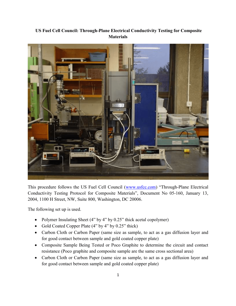
The assembly is placed in a Carver Incorporated # 3851-0 Model C Hydraulic Laboratory Press
(platens size = 6 inches by 6 inches) with a digital force display. A pressure of 1000 psi is placed on the sample or Poco graphite (both are typically a 2” diameter or 2.5” diameter disk that is 1/8” thick) and the electrical resistivity is measured. A Keithley Instruments 2440 Source Meter
(range from 5 x 10
-10
A to 5 A) and a Keithley Instruments 2182A Nanovoltmeter (range from 1 x 10
-9
V to 10 V) are used. A constant current (typically 10 to 100 mA) passes through the sample and the voltage drop is measured.
Equation 1 shows the resistance measured when the Poco graphite is used.
R
Poco
+ R
Circuit
+ R
Contact
= R
Measured
(1)
Since the electrical resistivity of the Poco graphite is known (1.5 mohm-cm), the resistance of the Poco graphite can be calculated as shown in Equation 2 below.
R
Poco
= (ER*t)/(A) (2)
Where:
R= resistance
ER= Electrical Resistivity t= thickness of Poco graphite
A= current
Using Equations 1 and 2, the circuit and contact resistance are determined. Then the resistance of the composite sample is determined by Equation 3.
R
Composite Sample
= R
Measured
- R
Contact
- R
Contact
(3)
10 measurements are typically taken using the Poco graphite sample with the sample removed from the press and rotated slightly between each measurement.
2
Then Equation 4 is used to calculate the electrical resistivity of the composite sample.
ER
Composite Sample
= (R
Composite Sample
)(Area
Composite Sample
)/(t
Composite Sample
) (4)
Where:
Area composite sample
=
r
2 for a circular disk t composite sample
= thickness, typically 1/8” or 0.3 cm
Typically 5 measurements are made on each composite sample with the sample removed from the press and rotated slightly between each measurement. Typically 4 different composite samples are tested for each composite formulation.
3


