SuggestedAnswerCh5
advertisement

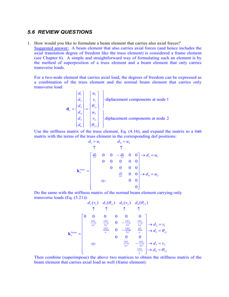
5.6 REVIEW QUESTIONS 1. How would you like to formulate a beam element that carries also axial forces? Suggested answer: A beam element that also carries axial forces (and hence includes the axial translation degree of freedom like the truss element) is considered a frame element (see Chapter 6). A simple and straightforward way of formulating such an element is by the method of superposition of a truss element and a beam element that only carries transverse loads. For a two-node element that carries axial load, the degrees of freedom can be expressed as a combination of the truss element and the normal beam element that carries only transverse load: d1 u1 d v diplacement components at node 1 2 1 d3 z1 de d 4 u2 d5 v2 diplacement components at node 2 d 6 z 2 Use the stiffness matrix of the truss element, Eq. (4.16), and expand the matrix to a 6x6 matrix with the terms of the truss element in the corresponding dof positions: d1 u1 d 4 u2 0 0 AE 0 0 d1 u1 2a 0 0 0 0 0 0 0 0 0 k truss e AE 0 0 d 4 u2 2a sy. 0 0 0 Do the same with the stiffness matrix of the normal beam element carrying only transverse loads (Eq. (5.21)): d 2 (v1 ) d3 ( z1 ) d5 (v2 ) d 6 ( z 2 ) AE 2a 0 0 0 0 0 0 3 EI z 3 EI z 3 EI z 3 EI z 0 2 a3 2 a3 2 a2 2 a 2 d 2 v1 2 EI 3 EI EI z z z 0 2 a2 d 3 z1 a a beam ke 0 0 0 3 EI z sy. 32EIa2z d5 v2 2 a3 2 EI z d 6 z2 a Then combine (superimpose) the above two matrices to obtain the stiffness matrix of the beam element that carries axial load as well (frame element): 0 0 AE 0 0 AE 2a 2a 3 EI z 3 EI z 3 EI z 3 EI z 0 2 a3 2 a3 2 a2 2 a2 2 EI 3 EI EI z z 0 2 a2z a a ke AE 0 0 2a 3 EI z 3 EI z sy. 2 a2 2 a3 2 EI z a The mass matrix can also be obtained by the same way of superimposing the mass matrix of the truss element (Eq. (4.17)) with the mass matrix of the beam element (Eq.(5.23)) as: 0 35 0 0 70 0 78 22a 0 27 13a 8a 2 0 13a 6a 2 Aa me 70 0 0 105 sy. 78 22a 8a 2 To obtain the force matrix, the same procedure can also be applied. The element force vectors of the truss element (Eq. (4.18)) and the beam element (Eq. (5.24)) are extended into 6x1 vectors and superimposed. If the element is loaded by external distributed forces fx and fy along the x-axis; concentrated forces fsx1, fsx2, fsy1 and fsy2; and concentrated moments ms1 and ms2, respectively at nodes 1 and 2, the total nodal force vector becomes f x a f sx1 f a f sy1 y 2 fya m s1 fe 3 f x a f sx 2 f y a f sy 2 2 f y3a ms 2 The final finite element equation for a beam element that carries axial load is k ed e m ed e f e 2. Calculate the force vector for a simply supported beam subjected to a vertical force at the middle of the span, when only one beam element is used to model the beam as shown in Figure 5-10. `` P 0 x, l=2a Figure 5-10 Simply supported beam modelled using one beam element. Suggested answer: In constructing finite element meshes, one usually and should include nodes at the location of the point loading. Nevertheless, if the point source of load does not occur at a node as shown above, it is possible to treat the point source as a special distributed load across the element. The point source, P, can be represented by a function q( x) P ( x 0) P ( x 0) where is the Dirac delta function defined generally by F ( x) ( x xo )dx F ( xo ) Therefore, by using Eq. (5.24), the force vector can be obtained by fe NT fb dV NT f s dS f V Sf 0 0 l T N P x 0 dx 0 0 0 N1 ( 0) P / 2 N ( 0) Pl / 8 P 2 F N ( 0) P / 2 3 N 4 ( 0) Pl / 8 Note that in doing the above, the point load source is converted to two “nodal forces” with shear forces and moments. However, one knows that in this case, for a simply supported beam, the two ends should have zero moments and hence there is clearly an approximation in this conversion. The FEM formulation guarantees the work done by the original concentrated force at the middle of the pan is equivalent to the nodal forces applied at the two ends. In practice, it is preferred to have a node located at the point external load for better accuracy and easy implementation (see Question 3). Further discussion: If a concentrated moment of M instead of force P is applied at the middle of the beam as shown in Figure 5-10a, what would be the external force vector? M l Figure 5-10a Simply supported beam modeled using one beam element. In this case, Eq. (5.24) can not be used, as it does not take the moment into consideration. Recall that the force vector is derived from the EXTERNAL work done in the Hamilton’s principle (see, Eq. (3.5)). Let’s now consider the work done by this external moment. Following Eq.(3.5), we have a W f ( x)m( x)dl a where is the rotation of the cross-section of the beam, and m is an external moment that distributed over the span of the beam. The point moment, M, can be represented again by the following function m( x ) M ( x a ) We then have a a a a W f ( x)m( x)dl ( x)M ( x a)dl M ( x a) M ( 0) Using now Eq.(5.5), we have ( ) 1 v a Using Eq.(5.12), the above equation becomes 1 v 1 N( ) de a a The derivatives of shape functions can be obtained using Eq.(5.14): N1 ( ) 14 (3 3 2 ) ( ) N 2 ( ) a4 (1 2 3 2 ) N 3 ( ) 14 (3 3 2 ) N 4 ( ) a4 (1 2 3 2 ) We therefore have 4a3 1 1 T 4 ( 0) 3 a 3 a de de 3 4a 4a 41 and the external work done should be 43aM M T 4 W f M ( 0) de 3M 4a 4M Note that the work done by the external force vector (that we want to obtain) should be W f dTe fe and it should be the same as the work done by the concentrated moment, which leads to 4a3 43aM 1 M or dTe fe dTe 43 M fe 34M 4a 4a 4M 41 This energy equivalence procedure is applicable for all other situations to obtain the external force vectors. 3. Calculate the force vector for a simply supported beam subjected to a vertical force at the middle of the span, when two beam elements of equal length are used to model the beam as shown in Figure 5-11 P l/2 l Figure 5-11 Simply supported beam modelled using two beam elements. Suggested answer: To obtain the force vector in this case, let us first “disassemble” the two elements and analyze the external forces and moments acting on each of them as shown below: P/2 P/2 1 2 Note that there is no distributed forces or moments and neither is there any concentrated moments, therefore, using Eq. (5.24), the force vector for element 1 can be obtained by fe1 NT f b dV NT f s dS f V Sf 0 0 0 0 0 0 0 P / 2 P / 2 0 0 0 Similarly for element 2, f e 2 N T f b dV V N T f s dS f Sf 0 0 P / 2 0 0 0 0 P / 2 0 0 0 0 To obtain the global force vector, the forces and moments of the middle, common node would have to be added up to give 0 0 0 0 P / 2 ( P / 2) P F 0 0 0 0 0 0 The above is the force vector due to external forces on the beam. 4. For a cantilever beam subjected a vertical force at its free end, how many elements should be used to obtain the exact solution for the deflection of the beam? (Hint): Review the worked example 5.1.


