Introductory Experiment I –Graphs
advertisement
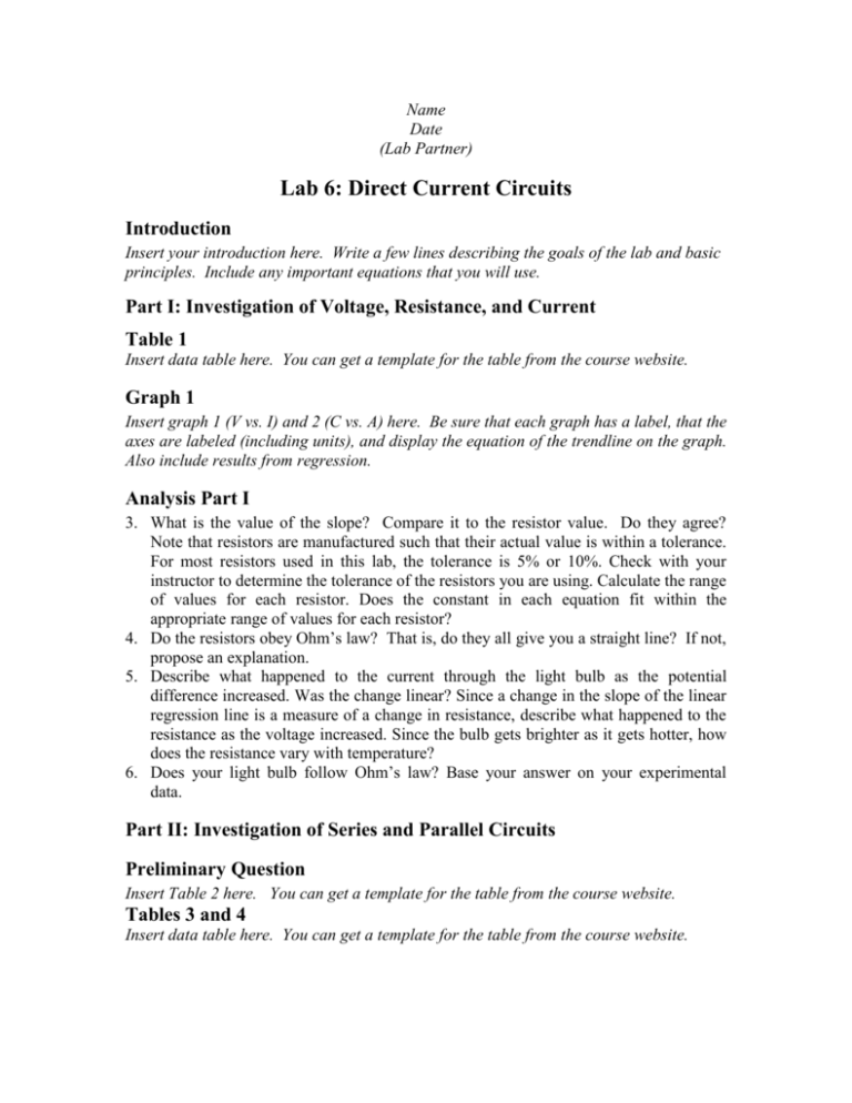
Name Date (Lab Partner) Lab 6: Direct Current Circuits Introduction Insert your introduction here. Write a few lines describing the goals of the lab and basic principles. Include any important equations that you will use. Part I: Investigation of Voltage, Resistance, and Current Table 1 Insert data table here. You can get a template for the table from the course website. Graph 1 Insert graph 1 (V vs. I) and 2 (C vs. A) here. Be sure that each graph has a label, that the axes are labeled (including units), and display the equation of the trendline on the graph. Also include results from regression. Analysis Part I 3. What is the value of the slope? Compare it to the resistor value. Do they agree? Note that resistors are manufactured such that their actual value is within a tolerance. For most resistors used in this lab, the tolerance is 5% or 10%. Check with your instructor to determine the tolerance of the resistors you are using. Calculate the range of values for each resistor. Does the constant in each equation fit within the appropriate range of values for each resistor? 4. Do the resistors obey Ohm’s law? That is, do they all give you a straight line? If not, propose an explanation. 5. Describe what happened to the current through the light bulb as the potential difference increased. Was the change linear? Since a change in the slope of the linear regression line is a measure of a change in resistance, describe what happened to the resistance as the voltage increased. Since the bulb gets brighter as it gets hotter, how does the resistance vary with temperature? 6. Does your light bulb follow Ohm’s law? Base your answer on your experimental data. Part II: Investigation of Series and Parallel Circuits Preliminary Question Insert Table 2 here. You can get a template for the table from the course website. Tables 3 and 4 Insert data table here. You can get a template for the table from the course website. Analysis Part II Section II-A: Series Circuits 1. What is the relationship between the three voltage readings: V1, V2, and VTOT? 2. Using the measurements you made for I and VTOT and your knowledge of Ohm’s law (V=IR), calculate the equivalent resistance (Req) of the circuit for the two series circuits you tested. 3. Study the equivalent resistance readings for the series circuits. Can you come up with a rule for the equivalent resistance (Req) of a series circuit with two resistors? 1. For each of the series circuits, compare the experimental results with the resistance calculated using your rule. In evaluating your results, consider the tolerance of each resistor by using the minimum and maximum values in your calculations. 2. Examine the currents you measured for the series circuits. What is the relationship between the total current and the currents through each of the resistors? Section II-B: Parallel Circuits 1. Using the measurements you made for I and VTOT and your knowledge of Ohm’s law, calculate the equivalent resistance (Req) of the circuit for the two parallel circuits you tested. 2. Study the equivalent resistance readings for the parallel circuits. Devise a rule for the equivalent resistance of a parallel circuit of two resistors. 3. What do you notice about the relationship between the three voltage readings V1, V2, and VTOT in parallel circuits? 4. Examine the currents you measured for the parallel circuits. What is the relationship between the total current and the currents through each of the resistors? 5. If the two measured currents in your parallel circuit were not the same, which resistor had the larger current going through it? Why? 6. Compare the total currents through the parallel circuits to the total current flowing through the series circuits. Which has the largest total current? Why? Conclusion Write a few concluding remarks. Sample Calculations Insert any sample calculations here. These may be added by hand.


