Valley Angles
HIP / VALLEY KERNELS
Dihedral angle turned through an angle of revolution
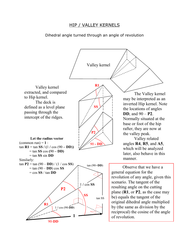
Valley kernel
Valley kernel extracted, and compared to Hip kernel.
The deck is defined as a level plane passing through the intercept of the ridges.
R1
SS
P2
Let the radius vector
(common run) = 1 : tan R1 = tan SS / ( 1 / cos (90 – DD ) )
= tan SS cos ( 90 – DD)
= tan SS sin DD
Similarly: tan P2 = tan (90 – DD ) / (1 / cos SS )
= tan (90 – DD ) cos SS
= cos SS / tan DD
P2
90 - DD tan (90
–
DD )
1 / cos SS
SS tan SS
R1
1 / cos (90DD )
1
90DD
The Valley kernel may be interpreted as an inverted Hip kernel. Note the locations of angles
DD , and 90 – P2 .
Normally situated at the base or foot of the hip rafter, they are now at the valley peak.
Valley related angles R4 , R5 , and A5 , which will be analyzed later, also behave in this manner.
Observe that we have a general equation for the revolution of any angle, given this scenario. The tangent of the resulting angle on the cutting plane ( R1 , or P2 , as the case may be) equals the tangent of the original dihedral angle multiplied by (the same as division by the reciprocal) the cosine of the angle of revolution.
VALLEY ANGLE RELATIONSHIPS:
R4B
,
R5B
,
A5B
,
DD
,
R1
Extracting a “Bird’s-Mouth” Kernel at the Valley Peak
Kernel shown as positioned at valley peak.
Dihedral Angle = 90 – A5B
Compare to the Valley kernel extracted directly from the roof. The geometry is the same, but note that the Valley pitch angle R1 is now the dihedral angle, while R5B serves as the “Valley pitch” angle for this model.
R1
R4B
DD
R5B
Kernel split into
Main and Adjacent sides along the plane of angle R1 , extracted, and rotated.
Kernel with the angles labeled. Remember that the standard model is a Hip kernel (refer to the diagram on the previous page). The angles located at the foot, or base , of a hip rafter will be found at the peak of a valley rafter.
For future reference, also note the location of dihedral angle 90 – A5B , which governs the value of the saw blade setting. Like angle C5 on the actual roof, A5B lies along the line between the “roof plane” of the kernel and the plumb plane through the long axis of the “hip” or “valley” on the kernel. Alternatively, consider the angle R4B as the miter angle, and 90 – R1 as the bevel angle.
VALLEY RAFTER ANGLE FORMULAS:
R4B
,
R5B
,
A5B
,
DD
,
R1 angle through another angle.
At this point, we have formulas for the rotation of one
Angles
R1
and
DD
are known quantities. Given this information, we can calculate
R4B
, the miter angle on the bottom face or shoulder of the valley rafter; simply rotate angle
DD
through angle
R1
: tan
R4B
= tan
DD
cos
R1
Angle
R5B
is the complement of the angle on the plane created by cutting a compound angle. We can find the value of
R5B
by rotating angle
R1
through angle
DD
: tan
R5B
= tan
R1
cos
DD
Another solution:
If cos (
Compound Face Angle
) = cos
Miter
cos
Bevel then cos (90 –
R5B
) = cos
R4B
cos (90 –
R1
) and sin
R5B
= cos
R4B
sin
R1
As for angle
A5B
:
Since tan (
Blade Angle
) = sin
Miter
/ tan
Bevel
tan
A5B
= sin
R4B
/ tan (90 –
R1
)
= sin
R4B
tan
R1
By comparing the angles in the “Bird’s-mouth” kernel to the Valley and Hip kernels, and making appropriate substitutions, it is possible to find further relationships.
However, for the time being, instead of dealing with abstract models that may be difficult to relate to the real world, the focus will be on the simplest calculations and geometry that may be derived from an examination of the proposed cut.
VALLEY RAFTER ANGLE FORMULAS:
R4P
,
R5P
,
A5P
, 90
- DD
,
R1
90 - R5P
R4P
R1
90 - SS
90 - DD
R4P
R5P
To calculate angles at the base or foot of a valley rafter, consider a kernel positioned below the rafter as shown in the diagram to the left. The “roof plane” of the kernel is parallel to the bottom shoulder of the valley rafter (imagine the rafter seated on the kernel).
Since a valley rafter is in essence an “upside-down” hip rafter, the angular values expected at the valley rafter. peak of a hip rafter are located at the
Dihedral Angle =
90 – A5P base
Using the angle rotation formulas: tan
R4P
= tan (90 –
DD
) cos
R1
= cos
R1
/ tan
DD tan
R5P
= tan
R1
cos (90 –
DD
)
= tan
R1
sin
DD
To determine the value of
A5P
, substitute the appropriate quantities in the equation for the saw blade angle:
If tan (
Blade Angle
) = sin
Miter
/ tan
Bevel then tan
A5P
= sin
R4P
/ tan (90 –
R1
)
= sin
R4P
tan
R1
of a
Notes re: Angle Formulas
When working with a framing square, the calculations for miter, bevel and cutting angles are best if given in terms of the tangent of the required angle. Angles are expressed as a value “over-12”, and since the tangent = rise / run, we have a trig function of a required angle suited for direct use on the square.
Slope
Rise
Generally:
Rise = Run
X
tan ( ANGLE )
For “over-12” measurements:
ANGLE Run
Rise = 12
X tan ( ANGLE )
If using a programmable calculator or spreadsheet to determine angular values, the tangent of an angle is not necessarily the best mode of calculation, since trig functions change sign according to quadrant. Recall that given a Total
Deck Angle > 90 degrees, it is possible for either
DD
or
D
to exceed 90 degrees. Subsequent calculations will be affected by the trig function chosen; the cosine of the angle always returns a positive value for the angles listed below.
The formulas were resolved using linear algebra, and are given without proof. Relationships between the peak and base values may be supplementary, rather than complementary, depending on the value of
DD
(base or peak) entered. Dihedral angle related values
C5
and
A5
may be 90 plus or minus the angle. cos (90
± C5
) = sin
SS
cos
DD cos
R1
= cos
SS
/ sin (90
± C5
) cos
P2B
= cos
DD
cos
R1 cos (90
± A5B
) = sin
R1
sin
DD cos
R5B
= cos
R1
/ sin (90
± A5B
) cos
R4B
= cos
DD
/ sin (90
± A5B
)


