Chap 8 First Order Circuits
advertisement

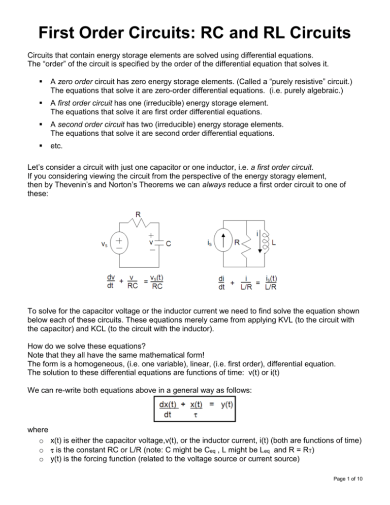
First Order Circuits: RC and RL Circuits Circuits that contain energy storage elements are solved using differential equations. The “order” of the circuit is specified by the order of the differential equation that solves it. A zero order circuit has zero energy storage elements. (Called a “purely resistive” circuit.) The equations that solve it are zero-order differential equations. (i.e. purely algebraic.) A first order circuit has one (irreducible) energy storage element. The equations that solve it are first order differential equations. A second order circuit has two (irreducible) energy storage elements. The equations that solve it are second order differential equations. etc. Let’s consider a circuit with just one capacitor or one inductor, i.e. a first order circuit. If you considering viewing the circuit from the perspective of the energy storagy element, then by Thevenin’s and Norton’s Theorems we can always reduce a first order circuit to one of these: To solve for the capacitor voltage or the inductor current we need to find solve the equation shown below each of these circuits. These equations merely came from applying KVL (to the circuit with the capacitor) and KCL (to the circuit with the inductor). How do we solve these equations? Note that they all have the same mathematical form! The form is a homogeneous, (i.e. one variable), linear, (i.e. first order), differential equation. The solution to these differential equations are functions of time: v(t) or i(t) We can re-write both equations above in a general way as follows: where o x(t) is either the capacitor voltage,v(t), or the inductor current, i(t) (both are functions of time) o is the constant RC or L/R (note: C might be Ceq , L might be Leq and R = RT) o y(t) is the forcing function (related to the voltage source or current source) Page 1 of 10 So to solve a first order circuit (i.e. solve for v(t) or i(t) ), we need to solve this differential equation. After some work (and taking a class in differential equations) we get the solution: The solution to a differential equation always has two parts: A forced response, xf(t), and a natural response, xn(t). (They have other names too.) Together they form the complete response, x(t). K is an arbitrary constant of integration that shows up in the natural response and is determined from the initial conditions. (There will be the same number of arbitrary constants as the order of the equation. In this case there is only one because it is a first order differential equation.) We can see from this that the solution to a first order circuit will depend on the type of forcing function, y(t), in the circuit. Consider the solutions for 4 different forcing functions: A Source Free Circuit The case of y(t) = 0 The solution is: A DC Circuit The case of y(t) = constant, M The solution is: alternatively : An exponential circuit The case of y(t) = Aebt The solution is: An ac circuit The case of y(t) = A sin(t + ) The solution is: Page 2 of 10 Notes about the natural response, xn(t): It is found by setting the input (forcing function) to zero. Its form is like the source free circuit but the amplitude depends on the forcing function and the initial energy storage. It is characteristic of the circuit, not of the sources (i.e. forcing functions) It will have the same number of arbitrary constants as the order of the differential equation. (These constants are determined from boundary conditions.) It provides a transition from the initial values of x (voltage or current) to the final value. It is also called the transient response. It is also called the complementary solution. It is also called the free response. Notes about the forced response, xf(t): It will be present forever. It is found by pretending that all switches have been closed for a long time. It has the same form as the forcing function. It will be the response of the circuit after the transient part has settled out. It is also called the particular solution or particular integral. it is also called the steady state response Notes about : It is called the time constant. It represents the time it would take the voltage or current to get to its final value if the initial rate stayed constant. x() = 0.63xinfinity + o.37x0 How long will it take for the voltage or current to get to its final value at its actual (and changing) rate of decay? (Answer: 5) Page 3 of 10 Response of a first order circuit with a constant source Here is the plot of the solution of an RL or an RC circuit with a constant source where the final value of current or voltage is less than the original value. x = xinfinity + [x0 - xinfinity] e– t/ where xinfinity < x0 Note: A larger value of means a longer time to reach its final value, i.e. a slower decay. Here is the plot of the solution of an RL or an RC circuit with a constant source where the final value of current or voltage is greater than the original value. x = x + [x0 - x] e– t/ where x > x0 Note: A larger value of means a longer time to reach its final value. Page 4 of 10 How do the values of R and C affect the time constant in an RC circuit? Question: For an RC circuit, large values of C or large values of R will cause a larger . Consider disconnecting the voltage source. Why would a large C or R cause the circuit to take a long time to discharge? (i.e. reach the final value of zero voltage across the capacitor.) Answer: A large value of C allows greater energy to be stored in the capacitor. A large amount of energy will require a longer time to be dissipated in the resistor. A large value of R means that power dissapated in it (p = v2/R) will be less for the same initial energy stored in the capacitor (i.e. the initial voltage, vo = vs). Hence it will take a longer time to dissipate the stored energy. How do the values of R and L affect the time constant in an RL circuit? Question: For an RL circuit, large values of L or small values of R will cause a larger . Consider disconnecting the current source. Why would a large L or a small R cause the circuit to take a long time to reach the final value of zero current through the inductor? Answer: A large value of L allows greater energy to be stored in the inductor. A large amount of energy will require a longer time to be dissipated in the resistor. A small value of R means that power dissapated in it (p = i2R) will be less for the same initial energy stored in the inductor (i.e. the initial current, io= is). Hence it will take a longer time to dissipate the stored energy. Page 5 of 10 The procedure to find the response of ANY first order dc circuit For a first order circuit with an inductor (RL circuit) and a constant source: It will ALWAYS have this form: iL(t) = if(t) + in(t) where if = iinfinity in = [i0 – iinfinity] e-t/ So you just need to find 3 things: 1. i0 to find this just find iL(0-): you know that iL(0-) = iL(0+) = i0 2. just find Leq and Req: = Leq /Req 3. iinfinity just consider the circuit after t >>> 0 and find i For a first order circuit with a capacitor (RC circuit) and a constant source: It will ALWAYS have this form: vC(t) = vf(t) + vn(t) where vf = vinfinity vn = [v0 – vinfinity] e-t/ So you just need to find 3 things: 1. v0 the find this just find vC(0-): you know that vC(0+) = vC(0-) = v0 2. just find Req and Ceq: = ReqCeq 3. vinfinity just consider the circuit after t >>> 0 and find v Page 6 of 10 The Unit-Step Forcing Function Singularity functions are discontinuous functions or have discontinuous derivatives. One example is the unit-step forcing function or the unit-impulse function. This is the definition of the unit-step forcing function: u(x) = 0 for all x < 0 u(x) = 1 for all x > 0 note: this is not defined for x=0 Consider x = ( t – to) u ( t – to) = 0 for all t < to u ( t – to) = 1 for all t > to note: this is not defined for t = to The unit step forcing function is zero when the argument is less than zero and 1 when the argument is greater than zero. Page 7 of 10 We can model switches with this unit step forcing function. Consider a voltage source being switched into a general network: *equivalent means the voltage current characteristic of the two networks are identical. This is not the exact equivalent because the voltage across the switch and battery is completely unspecified. This will be equivalent if we don’t care about t < t o and if currents which flow from the two networks are identical at t = to. Consider a current source beingswitched into a general network: Page 8 of 10 The rectangular voltage pulse: v(t) = 0 for all t < to v(t) = Vo for all to < t < t1 v(t) = 0 for all t1 < t note: this is not defined for t = to or for t = t1 We can model this pulse with unit step forcing functions: v(t) = Vou(t - to) – Vou(t - t1) Page 9 of 10 A note about stability: f(t) = ff (t) + fn(t) fn(t) = Ae-t/ If > 0 then lim fn(t) as t approaches infinity = 0 i.e. the transient response dies out. This is stable. The forced response depends on the input to the circuit. However, if < 0 then lim fn(t) as t approaches infility is infinity! i.e. the transient response does not die out! It increases exponentially! This is unstable. The forced response is negligible. For the case of instability, it looks as if the natural response will grow without bound. This looks scary! But don’t worry. This is not the case. It will grow until something happens such as the saturation of an op-amp, or a dependant source, or the destruction of a circuit element. None of these things are desirable and so it is usually not desirably to have an unstable circuit. Differential Operators An operator is a symbol that represents a mathematical operation. We define the differential operator, s, such that: so = 1 s1x = dx/dt s2x = d2x /dt2 snx = dnx /dtn 1/s = The advantage is that s can be treated algebraically. So differential equations can be transformed into algebraic ones, solved and then transformed back into the differential equations. The operator 1/s satisfies the usual rules of algebraic manipulations including commutative: s x 1/s = 1/s x s = 1 This is actually only true when x(-infinity) = 0 This doesn’t bother us because we require all capacitor voltages and inductor currents to be 0 at t = -infinity Page 10 of 10


