Statistics --
advertisement
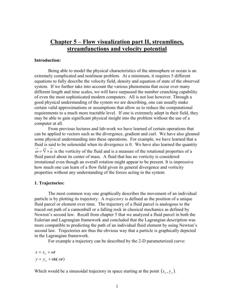
Chapter 5 – Flow visualization part II, streamlines, streamfunctions and velocity potential Introduction: Being able to model the physical characteristics of the atmosphere or ocean is an extremely complicated and nonlinear problem. At a minimum, it requires 5 different equations to fully describe the velocity field, density and equation of state of the observed system. If we further take into account the various phenomena that occur over many different length and time scales, we will have surpassed the number crunching capability of even the most sophisticated modern computers. All is not lost however. Through a good physical understanding of the system we are describing, one can usually make certain valid approximations or assumptions that allow us to reduce the computational requirements to a much more tractable level. If one is extremely adept in their field, they may be able to gain significant physical insight into the problem without the use of a computer at all. From previous lectures and lab-work we have learned of certain operations that can be applied to vectors such as the divergence, gradient and curl. We have also gleaned some physical understanding into these operations. For example, we have learned that a fluid is said to be solenoidal when its divergence is 0. We have also learned the quantity u is the vorticity of the fluid and is a measure of the rotational properties of a fluid parcel about its center of mass. A fluid that has no vorticity is considered irrotational even though an overall rotation might appear to be present. It is impressive how much one can learn of a flow field given its general divergence and vorticity properties without any understanding of the forces acting in the system 1. Trajectories: The most common way one graphically describes the movement of an individual particle is by plotting its trajectory. A trajectory is defined as the position of a unique fluid parcel or element over time. The trajectory of a fluid parcel is analogous to the traced out path of a cannonball or a falling rock in classical mechanics as defined by Newton’s second law. Recall from chapter 5 that we analyzed a fluid parcel in both the Eulerian and Lagrangian framework and concluded that the Lagrangian description was more compatible to predicting the path of an individual fluid element by using Newton’s second law. Trajectories are thus the obvious way that a particle is graphically depicted in the Lagrangian framework. For example a trajectory can be described by the 2-D parameterized curve: x xo t y y o sin( t ) Which would be a sinusoidal trajectory in space starting at the point xo , y o . 1 trajectory of x=1+2*pi*t y=1+sin(2*pi*t) 2.5 2 1.5 y 1 0.5 0 -0.5 1 2 3 4 x 5 6 7 Figure 1 - Graph of trajectory of x xo t and y y o sin t for xo y o 1 and 2 2. Streamlines: As we found out in Chapter 5, even though the Lagrangian framework is the most direct way to apply Newton’s laws, it is usually computationally cumbersome in most circumstances as a method of describing the overall flow field in a given domain. An alternative approach is to utilize the Eulerian framework where one describes the properties of a fluid at an arbitrary point in space and time. One can imagine measuring a flow field in the Eulerian Framework by placing many evenly spaced current meters over the fluid domain. The recorded data can be used to create an overall description of the flow field that is defined by the location and time that an observation was recorded. Given that we are measuring the flow field throughout the whole domain at a given time, a trajectory is not a plausible graphical description for the overall flow field. Instead, we use an approach where we create a set of streamlines or curves throughout the domain where each streamline represents the tangential velocity of the flow field at a given point. Given a velocity field u ux, y i vx, y j w( x, y) k and length element ^ ^ ^ ^ ^ ^ d dx i dy j dz k , one is able to describe the spatial locations of these curves using the equation: dx dy dz u v w (1) To derive equation (1) we use the definition that the length element d is parallel to the velocity field u at a given point. Recall that two vectors are parallel to each other if their cross product is equal to 0 , u d 0 , Thus from our defined general velocity field and length element we see that 2 ^ ^ ^ i j k ^ ^ ^ u d u v w vdz wdy i wdx udz j udy vdx k 0 dx dy dz The equality to vector 0 implies that each of the of the above three terms is equal to 0 so vdz wdy 0 v w for the first term dy dz wdx udz 0 w u for the second term and dz dx udy vdx 0 u v for the third term dx dy Relating these three equalities and the use of the transitive property gives equation (1). ^ ^ Excercise 1: Given the velocity field u y i x j , show that the streamlines are a set of concentric circles using equation 1. Now that we have a mathematic definition of a streamline in equation (1), the question becomes what do streamlines look like? Recall the process leading to the equation (1) in the first place was to find a set of curves that are everywhere parallel to the velocity field within the fluid domain. Figure 2 shows a good example of how streamlines relate to the current field. Notice that the contours are everywhere parallel to the vectors. superposition of strealines over velocity filed vectors 1 0.8 0.6 0.4 y 0.2 0 -0.2 -0.4 -0.6 -0.8 -1 -1 -0.8 -0.6 -0.4 -0.2 0 x 0.2 0.4 0.6 0.8 1 ^ ^ Figure 2 – superposition of streamlines contours over the velocity field u y i x j 3 3. Stream functions: A common simplification for fluids in the atmosphere and the ocean is to assume incompressibility; meaning the density of the fluid throughout the domain is spatially constant. We will see in a later chapter that assuming a constant density field is the same as assuming the flow field is divergence free. For now, we will accept that fact that the fluid is incompressible and that u 0 . With a little examination of the dimensional scales of the various physical parameters, one can observe that incompressibility is actually a safe assumption to make under most normal circumstances in the ocean environment and even for many cases in the atmosphere. The general mathematical term for a vector u that obeys the restriction u 0 throughout the domain is that u is solenoidal. Let us examine the properties of such a field. One way to ensure that the vector u obeys u 0 is to exploit the commutability of the partial derivative operator and assume that there exists a scalar x, y, t such that, u y (2) v x Excercise 2: Show that if you are given equation (2) that u 0 and thus the velocity field is solenoidal. is a unique function of the flow field and is called the streamfunction. Notice that another way of expressing equation (2) is in terms of a cross product of the gradient of the stream function ^ k h where h ^ ^ i j x y ^ It is left as an exercise for the student to verify that u k h One major feature of streamfunctions is that they are constant along streamlines. To see this we must examine the differential of the stream function d x, y dx dy vdx udy 0 x y (3) 4 where equations (1) and (2) have been used in the second equality to obtain zero for an answer for the differential. The proof leading to equation (3) shows that the lines formed by constant streamfunctions are the same as the streamlines of the velocity field. In other words, d 0 , contains the same information as equation (1). This result is significant since we have discovered a scalar function that can provide all the physical properties of the fluid velocity field. Given a 2-D flow field that obeys the constraint, u 0 , we only need one unique scalar function to describe the entire flow field and have thus reduced the number of needed equations by half. 4. Velocity Potential: Irrotational flow – An irrotational flow is simply defined as a flow field with no vorticity, u 0 . Recall that the vorticity at a point is a measure of the rotation of the fluid parcel about its center of mass located at that point. Vorticity is not indicative of the apparent overall circulation of the fluid about a center of rotation. For example, look at ^ ^ 1 the vector field and vorticity of the velocity field u 2 y i x j . 2 x y One can relate a 2-D irrotational velocity field to a scalar x, y called the velocity potential as u x, y ux, y i vx, y j x, y . With components u x (4) v y By relating a velocity field to a scalar quantity like in equation (4) we can ensure that the velocity field is irrotational as can be seen in the following exercise. ^ ^ Excercise 3: Show that if a 2-D flow field satisfies ux, y x, y , that u 0: One other property of the velocity potential is that its contours are perpendicular to ^ ^ streamlines contours. As an example, for the velocity field u x i y j , the streamline contours can be shown to be a set of lines directed radially outward in the graph while the velocity potential lines are a set of concentric circles. Figure 3 superimposes the velocity potential contours on top of the stream function contours. We can see that the two sets of contours are perpendicular. 5 streamlines and velocity potential contours for the velocity field u=x v=y 2 Streamline contours y 1.5 1 Velocity potential contours 0.5 0.5 1 1.5 2 x Figure 3 – Streamlines are shown as a set of lines directed radially outward and are perpendicular to velocity potential contours which are shown as segments of concentric ^ ^ circles for the velocity field u x i y j . The domain was specified only over 0.5 x, y 2 due to issues of the streamline being undefined at the origin for the graph. It is left as an exercise to the reader to formally prove that streamfunction and velocity potential contours are perpendicular. 5. Flow fields that are both irrotational and solenoidal. If a flow field satisfies both u 0 and u 0 , then both a streamfunction and a velocity potential exist for the flow field as defined by equations (2) and (4). Let us examine if any additional equations can be derived if the flow field satisfies both of the above properties. Given the streamfunction defined in equation (2), we can apply the irrotational ^ requirement, u k 0 to obtain a differential equation for as follows: ^ i ^ u k 0 x u ^ j y v ^ k ^ v u z k 0 x y 0 Substitution of equation (2) now shows: 6 x x y y Where 2h 0 2h 0 2 2 x 2 y 2 In other words use of the solenoidal nature of the streamfunction along with the assumption that the flow field is irrotational leads to the horizontal 2-D Laplace’s equation 2h 0 (5) We can use similar analysis with the velocity potential along with the assumption the flow field is solenoidal to obtain a related equation. Exercise 4: Given the velocity potential equations from equation (4) and the fact that the velocity field is solenoidal, u 0 , derive the following equation 2h 0 (6) We can see from equations (5) and (6) that, when the flow field is irrotational and solenoidal, both the velocity potential and stream function satisfy the 2-D Laplace’s equation: 2 2 0 x 2 y 2 2 2 0 x 2 y 2 Either equation (5) or (6) as well as a set of non-trivial boundary conditions, are sufficient to obtain a unique solution for either scalar function. The only additional restriction imposed is that the flow field needs to be both solenoidal and irrotational. At no point in the above discussion was it necessary to find the pressure field or consider any other forces. This is a remarkable result in the end, although the circumstances might be considered a bit limited we can see how far one can go in obtaining a solution with proper understanding of the kinematics of the problem. Further, the solenoidal and irrotational restrictions on the flow field might not be as limiting as you might think. Engineers use this type of flow field as a starting point for analyzing the details of aerodynamic flight. You may ask yourself if it is a good starting point for atmospheric or oceanic flow as well. We will be able to answer this question better after a couple more chapters. 7


