10. Three-phase systems.
advertisement
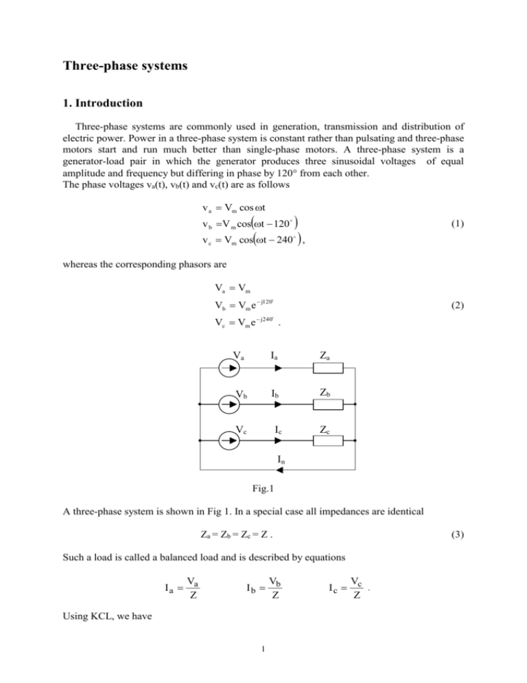
Three-phase systems 1. Introduction Three-phase systems are commonly used in generation, transmission and distribution of electric power. Power in a three-phase system is constant rather than pulsating and three-phase motors start and run much better than single-phase motors. A three-phase system is a generator-load pair in which the generator produces three sinusoidal voltages of equal amplitude and frequency but differing in phase by 120 from each other. The phase voltages va(t), vb(t) and vc(t) are as follows v a Vm cos t cost 240 , v b V m cos t 120 v c Vm (1) whereas the corresponding phasors are Va Vm Vb Vm e j120 (2) Vc Vm e j240 . Va Ia Za Vb Ib Zb Vc Ic Zc In Fig.1 A three-phase system is shown in Fig 1. In a special case all impedances are identical Za = Zb = Zc = Z . (3) Such a load is called a balanced load and is described by equations V Ia a Z V Ib b Z Using KCL, we have 1 V Ic c . Z I n Ia I b Ic 1 Va Vb Vc , Z (4) where Va Vb Vc Vm 1 e j120 e j240 1 3 1 3 0. Vm 1 cos120 j sin 120 cos 240 j sin 240 Vm 1 j j 2 2 2 2 Setting the above result into (4), we obtain In 0 . (5) Since the current flowing though the fourth wire is zero, the wire can be removed (see Fig.2) Va Ia Z Vb Ib Z Vc Ic Z n’ n Fig. 2 The system of connecting the voltage sources and the load branches, as depicted in Fig. 2, is called the Y system or the star system. Point n is called the neutral point of the generator and point n’ is called the neutral point of the load. Each branch of the generator or load is called a phase. The wires connecting the supply to the load are called the lines. In the Y-system shown in Fig. 2 each line current is equal to the corresponding phase current, whereas the line-to-line voltages ( or simply line voltages ) are not equal to the phase voltages. 2 Y-connected systems Now we consider the Y-connected generator sources ( see Fig. 3). 2 Va a Vb b Vc c Vab n Vca Vbc Fig.3 The phasors of the phase voltages can be generally written as follows Va V Vme j Vb Ve j120 Vc Ve j240 o . (6) o We determine the line voltages Vab, Vbc, Vca ( see Fig.3). Using KVL, we obtain 1 3 3 3 Vab Va Vb Va 1 j Va j 2 2 2 2 2 2 3 3 j tan 1 Va e 2 2 3 3 Va 3e j30 . Thus, o Vab Va 3 e j30 . (7) holds and similarly we obtain o Vbc Vb 3 e j30 (8) o Vca Vc 3 e j30 . 3 (9) The phasor diagram showing the phase and line voltages is shown in Fig.4. Vab Vc 30 Va 30 Vca 30 Vb Vbc Fig.4 Thus, the line voltages Vab, Vbc, Vca form a symmetrical set of phasors leading by 30 the set representing the phase voltages and they are 3 times greater. Vab Vbc Vca 3 Va . (10) The same conclusion is valid in the Y connected load ( see Fig.5). a Za=Z Va Vab Vca Zc=Z Zb=Z Vc Vb b Vbc c Fig.5 4 3. Three-phase systems calculations When the three phases of the load are not identical, an unbalanced system is produced. An unbalanced Y-connected system is shown in Fig.1. The system of Fig.1 contains perfectly conducting wires connecting the source to the load. Now we consider a more realistic case where the wires are represented by impedances Zp and the neutral wire connecting n and n’ is represented by impedance Zn ( see Fig.6). Va n Zp a Ia Vb b Ib Vc c Zp Zp Ic Zn a’ Za b’ Zb c’ Zc n’ In Vn Fig.6 Using the node n as the datum, we express the currents Ia, Ib, Ic and In in terms of the node voltage Vn Ia Va Vn Za Zp (11) Ib Vb Vn Zb Zp (12) Ic Vc Vn Zc Zp (13) In Vn . Zn (14) Hence, we obtain the node equation Vn Va Vn Vb Vn Vc Vn 0 Z n Za Z p Z b Z p Z c Z p Solving this equation for Vn, we have Va Vb Vc Za Zp Zb Zp Zc Zp Vn . 1 1 1 1 Zn Za Zp Zb Zp Zc Zp 5 (15) The above relationships enable us to formulate a method for the analysis of three-phase systems. The method consists of three steps as follows: (i) ( ii ) ( iii ) Determine Vn using (15) Calculate the currents Ia, Ib, Ic and In applying (11) - (14). Find the phase and line voltages using Kirchhoff’s and Ohm’s laws. When the neutral wire is removed, the system contains three connecting wires and is called a three-wire system. In such a case we set Z n into (15) Va Vb Vc Za Zp Zb Zp Zc Zp Vn . (16) 1 1 1 Za Zp Zb Zp Zc Zp The balanced system can be considered as a special case of the unbalanced system, where Za = Zb = Zc = Z. Using (16), we obtain Vn 1 Va Vb Vc Z Zp 3 Z Zp 0 . (17) Consequently, the relationships (11)-(13) reduce to Ia Va Z Zp (18) Ib Vb Z Zp (19) Ic Vc . Z Zp (20) Since Vb Va e j120 and Vc Va e j240 , we have Ib Ia e j120 and Ic Ia e j240 . Hence, we need to calculate Ia only using (18), which can be made applying the one-phase circuit described by equation (18) shown in Fig.7. Ia Zp Va Va Z n’ n Fig.7 6 This means that the analysis of a balanced three-phase system can be reduced to the analysis of one-phase system depicted in Fig.7. Example Let us consider three-phase system shown in Fig.8. The system is supplied with a balanced three-phase generator, whereas the load is unbalanced. The effective value of the generator phase voltage is 220V, the impedance of any connecting wire is Z p 2 j2 and the phase impedances of the load are Za 2 j4 , Zb 4 j2 , Zc 2 j4 . We wish to determine the line currents. Va Zp Vb Zp Ia Vab Ib b n Vca Vc Za a Zp Ic c Zb n’ Vbc Zc Vn Fig.8 Since the circuit of Fig.8 is a three-wire system, we apply equation (16) to compute Vn. The phase generator voltages are Va 220 2 V 1 3 155.56 j269.44 V Vb Va e j120 220 2 j 2 2 1 3 155.56 j269.44V . Vc Va e j240 220 2 j 2 2 Using (16), we find 220 2 155.56 j269.44 155.56 j269.44 4 j6 6 4 j6 Vn 97.5 j61.2V . 1 1 1 4 j6 6 4 j6 Next, we compute the line currents using (11)-(13) 7 4 Ia Va Vn 220 2 97.5 j61.2 23.49 j19.94A Za Z p 2 j4 2 j2 Ib Vb Vn 155.56 j269.44 97.5 j61.2 42.18 j34.70A Zb Zp 4 j2 2 j2 Ic Vc Vn 155.56 j269.44 97.5 j61.2 18.68 j54.63A . Zc Z p 2 j4 2 j2 Power in three-phase circuits In the balanced systems, the average power consumed by each load branch is the same and given by ~ Pav Veff Ieff cos (21) where Veff is the effective value of the phase voltage, Ieff is the effective value of the phase current and is the angle of the impedance. The total average power consumed by the load is the sum of those consumed by each branch, hence, we have ~ Pav 3Pav 3Veff Ieff cos (22) In the balanced Y systems, the phase current has the same amplitude as the line current Ieff Ieff L , whereas the line voltage has the effective value Veff L which is 3 times greater than the effective value of the phase voltage, Veff L 3Veff . Hence, using (22), we obtain Pav 3 Veff L Ieff L cos 3 3 Veff L Ieff L cos (23) Similarly, we derive Px 3 Veff L I eff L sin . (24) In the unbalanced systems, we add the powers of each phase Pav Veff a I eff a cos a Veff b I eff b cos b Veff c I eff c cos c (25) Px Veff a I eff a sin a Veff b I eff b sin b Veff c I eff c sin c . (26) In order to measure the average power in a three-phase Y-connected load, we use three wattmeters connected as shown in Fig.9. The reading of the wattmeter W1 is PW1 1 1 Re Va Ia Vm a I m a cos a Veff a I eff a cos a Pa . 2 2 8 * a’ Ia Za W1 * Va Ib * b’ Zb W2 n’ * Vb * * Zc Ic c’ W3 Vc Fig. 9 Similarly, W2 and W3 measure the average power of the load branch b and c, respectively. Thus, the sum of the three readings will give the total average power. This method of the average power measurement is valid for both balanced and unbalanced Y-connected loads. Note that in the case of a balanced Y-connected load all three readings are identical and therefore we use only one wattmeter. For measuring average power in a three-phase three-wire system, we can use a method exploiting two wattmeters. In this method two wattmeters are connected by choosing any one line as the common reference for the voltage coils of the wattmeters. The current coils are connected in series with the other two lines ( see Fig.10) and the asterisk terminals of each wattmeter are short-circuited ( see Fig.10). * Ia a * Vac W1 * b Ib W2 Load * Vbc c Ic Fig.10 The indications of the wattmeters are (27) (28) PW1 1 Re Vac Ia , 2 PW2 1 Re Vbc Ib . 2 9 The load is shown in Fig.11. Va Ia a Vac b Ib Vb Vbc c Ic Vc Za Zb Zc Fig.11 Since Vac = Va - Vc and Vbc = Vb - Vc, we obtain PW1 PW2 1 1 Re Va Vc Ia Va Ia Vc Ia , 2 2 1 1 Re Vb Vc Ib Vb Ib Vc Ib . 2 2 The sum of PW1 and PW2 gives PW1 PW2 1 Re Va I a Vb I b Vc I a I b . 2 (29) Currents Ia, Ib, Ic satisfy KCL Ia + Ib + Ic = 0 Hence, it holds Ia + Ib + Ic = 0 , or Ia + Ib = - Ic . (30) Substituting (30) into (29) we have PW1 PW2 1 Re Va I a Vb I b Vc I c Pav . 2 (31) Equation (31) says that the sum of the two wattmeters readings in a Y-connected system equals the total average power consumed by the load. Let us consider a balanced Y-connected load and calculate the instantaneous power delivered by the generator to the load p t va t ia t vb t i b t vc t ic t , where 10 (32) va t Vm cos t cost 240 v b t Vm cos t 120o vc t Vm and (33) o i a t Vm cost cost 240 . i b t Vm cos t 120 i c t Vm (34) where v a t , v b t , v c t are the voltages of the load branches, i a t , i b t , i c t are the currents of the load branches and is the angle of the load impedance. We substitute (33)-(34) in (32) p t VmI m[cos t cost cos t 120o cos t 120o cos t 240o cos t 240o ] and use the trigonometric identity cos x cos y 1 cos x y cos x y , 2 finding p t 1 VmI m 3cos cos2t cos 2t 240o cos 2t 480o . 2 Since cos 2t cos 2t 240o cos 2t 480o 0 we obtain pt 3 Vm I m cos 3Veff I eff cos Pav 2 (35) Thus, the total instantaneous power p(t) delivered by a three-phase generator to the balanced load is constant and equals the average power consumed by the load. 11
