Darragh-ODonoghue
advertisement
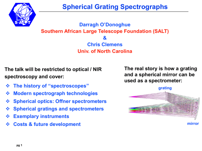
Spherical Grating Spectrographs Darragh O’Donoghue Southern African Large Telescope Foundation (SALT) & Chris Clemens Univ. of North Carolina The talk will be restricted to optical / NIR spectroscopy and cover: The history of ‘‘spectroscopes’’ Modern spectrograph technologies The real story is how a grating and a spherical mirror can be used as a spectrometer: grating Spherical optics: Offner spectrometers Spherical gratings and spectrometers Exemplary instruments Costs & future development pg 1 mirror Spherical Grating Spectrographs 19th Century Spectroscopes Prism Joseph von Fraunhofer’s drew the “lines” of the solar spectrum using the spectroscope he invented in 1820 JvF demonstrating his spectroscope Babinet and Simms introduced the collimator in France (1839) and England (1840) respectively. pg 2 Kirchoff and Bunsen used the spectroscope to gain the first understanding of the physical nature of spectral lines, discovering many elements Telescope Spherical Grating Spectrographs Diffraction Gratings Replace Prisms • The first (not very useful) diffraction gratings were made by David Rittenhouse in Philadelphia in 1785 and von Fraunhofer in the 1821: they strung hairs/wires between two finely-threaded screws. • In the late 1800s, Rowland made very accurate engines for ruling gratings on speculum which became the dispersers almost exclusively used for several decades all over the world. • Holographic gratings were invented in the late 1960s, and are made by etching photoresist with a powerful laser interference pattern; but their efficiency is modest because they are surface relief gratings without a blaze. pg 3 40 30 20 (%) 10 Dichromated gelatin Overall telescope + instrument efficiency vs wavelength 0 • High efficiency Volume Phase Holographic (VPH) gratings, which have refractive index variations “written” by an interferogram, came into astronomy in the 1990s, and have since become the dispersing element of choice. 300 400 500 600 700 800 (nm) Spherical Grating Spectrographs Mirrors in spectrographs • Until the end of the 19th century, collimators and cameras of spectroscopes were exclusively comprised of lenses. • Mirrors were introduced by Ebert (1889) & Fastie (1952), and Czerny & Turner (1930): but suffered from poor image quality and field of view. • With the invention of corrector plates by Schmidt (1931) and Maksutov (1944), astronomical spectrographs adopted catadioptric designs from ~1950. Ebert (1889)-Fastie (1952) pg 4 Czerny-Turner (1930) Almost all commercial instruments are of the Czerny-Turner design (but with correction) Catadioptric spectrographs from 1950 - ~1980s Spherical Grating Spectrographs Modern Optical / NIR Spectrographs Modern astronomical spectrographs require high multiplexing, and high efficiency to target very faint objects. Technology has been pushed to the limits: • Mirrors have gone out of favour owing to obscuration in the beam by the detector; lenses have made a comeback. But there has been a price: • Many lens elements are required (10-20) which are often large & heavy: up to 600 mm in diameter: costly and optomechanically challenging. • Almost all designs include one or more CaF2 / FK51 elements: CaF2 has wonderful dispersion properties but it is expensive, and mechanically and thermally fragile • To meet alignment tolerances of ~25 micron, optomechanics are hard. • Expensive anti-reflection coatings are required. • As telescope size increases, so does the spectrograph: a 10 m telescope may typically have a low/med res spectrograph of ~2 metre in linear dimension. ELTs are facing a x3 further increase. pg 5 Spherical Grating Spectrographs IMACS on Magellan 600 mm GMOS on Gemini 1m 1m MOBIE on TMT RSS on SALT 1.8 m pg 6 ½ the lenses are CaF2 Spherical Grating Spectrographs Is There An Easier Way? Revisiting mirrors: A major problem is self-obscuration – the detector sitting in the beam Solution: use mirrors off-axis Mirrors have 4 x the focusing power of lenses, so usually only 1 needed Focal length (mirror) = R / 2; focal length (plano-convex lens) ~ 2 R Mirror optical designs are usually very compact (they are folded) Off-axis mirror usage - what is the problem? Answer – huge astigmatism Image 1 mm (not 2 CCD pix = 30 microns) pg 7 Point source 30 mm off axis 50 mm, F/4 spherical mirror Spherical Grating Spectrographs Enter The Dyson and Offner 1-to-1 Relays Offner relay Image Invented in 1973 by A. Offner for lithography Identical spherical 3rd mirror, radius R Convex 2nd mirror, radius R/2 Concave spherical 1st mirror radius R Object EXCELLENT image quality: corrected for all 5 primary optical aberrations: • The astigmatism from the first reflection is balanced by equal and opposite astigmatism from the third as well as … • … field curvature balanced. True only if Petzval sum is 0: ∑ 1 / Ri = 0 , Ri is the radius of the i-th mirror Offner: (1 / R) - (2 / R) + (1 / R) = 0 pg 8 1st mirror 2nd mirror 3rd mirror Spherical Grating Spectrographs Offner Spectrometers: Replacing the convex secondary in an Offner relay by a convex grating was suggested by Thevenon, as reported by Mertz (1977), thereby producing an imaging spectrometer using a curved disperser. The light impacting the grating is not collimated, spherical mirrors provide the focusing power in an excellent imaging design, and their offaxis deployment means no obscuration. Spectrum on detector Tertiary mirror Convex grating Primary mirror Telescope pg 9 Entrance Slit Spherical Grating Spectrographs Collimated and Spherical Wavefronts Imagers and Spectrometers Since Fraunhofer, Babinet, Simms, Kirchoff and Bunsen, spectrometers have used flat dispersers (prisms and gratings), requiring collimators and cameras to turn spherical wavefronts from point sources (or slits) into flat wavefronts and back again. Offner optics based solely on spherical wavefronts. They are simple, compact (no collimator needed; folded), and have excellent image quality. Offner spectrometers have almost exclusively been used on space platforms: Earth observation satellites (from JPL): Mouroulis and collaborators Solar system missions (e.g. Cassini) Astronomy satellites (e.g. Gaia) The ‘fly in the ointment’ is: spherical dispersers are required. Convex gratings are hard to make and expensive (Rowland produced concave mirror gratings, not used in astronomy because of the limited field of view and efficiency) pg 10 Spherical Grating Spectrographs Needed: An inexpensive, efficient convex grating As mentioned, VPH gratings are the dispersers of choice for optical/NIR instruments because of their remarkable efficiency (w.r.t. surface relief gratings). My co-author, Chris Clemens, is one of only ~3 commercial suppliers of astronomical VPH gratings in the world. In 2012 February, Chris succeeded in making a prototype spherical VPH grating for use in a spectrometer I designed, and which we call the Half Offner. pg 11 Spherical Grating Spectrographs The first “Half Offner”-type spectrograph design using VPH gratings • The grating is used in double pass: on the first pass, the light is undiffracted (i.e. in zero order) • After reflection off the rear surface, it is diffracted efficiently in first order Lens 2 Reflective rear surface Lens 1 12 VPH pg grating: dichromated gelatin Spherical Grating Spectrographs Proof Of Concept Prototype: 2012 May-June Design, procurement, commission and testing in 6 wks • • • • • 1 x off-the-shelf spherical mirror, 50 mm in diameter, from Optosigma 2 x off-the-shelf meniscus lenses from JML Optical … … turned into a curved VPH grating in Chris’ lab Some optical bench fixturing We only got eyeball estimates of performance (due to time limits): looked good..BUT measurements still needed 20 mm Layout of the mini prototype pg 13 Resulting spectrum Spherical Grating Spectrographs A new vista in spectrometer design has opened Design space is largely unexplored. Here are the spherical grating spectrometers of which I am aware: Offner spectrometers Dyson spectrometers Headwall spectrometer. Unknown to us at the time we designed and built the “toy” Half Offner, Headwall Photonics have a patent on a design very similar to the Half Offner, but with a surface relief convex grating (only information is in the patent) An entirely new and even simpler design arises from the realization that the astigmatism of a spherical mirror, used off-axis, is perfectly balanced by the astigmatism of a spherical grating. The: Spherical Transmission Grating Spectrometer pg 14 Spherical Grating Spectrographs STGS-type spectrometers ‘Ideal’ spherical transmission grating Entrance slit Diffraction-limited image quality: almost all light inside Airy disc Focal plane 5200-6900 A R ~ 1000 A real system: a spherical VPH transmission grating: Spherical mirror 30 micron boxes: 2 CCD pixels A replacement for the Czerny-Turner design? pg 15 500 mm Teaching instruments? Spherical Grating Spectrographs STGS-type double beam spectrometer Red arm: 6350-8400 A Undiffracted in first order by passage through G1 G2 “Reverse” STGS Entrance slit G1 M2 “Forward” STGS Diffracted in first order by G1 Blue arm: 5200-6900 A M1 Light not diffracted in first order by G1 (via M1) passes to G2 (via M2) No dichroic break, maximum efficiency at overlapping wavelengths pg 16 Spherical Grating Spectrographs Real instruments 1: STGS spectrometer: VIRUS-like STGS ** Unobscured ** Smaller optics 1 spherical mirror 3 small spherical lenses 40 micron spatial resolution pg 17 Spherical camera mirror Aspheric corrector Fieldflattening lens and CCD (in beam) VPH grating both have: 3400 – 5700 Ang Resolution 700 - 1200 60 mm slit Spherical collimator mirror Fold mirror Slit & field lens HET Virus • • • • • • ** Obscured (detector in beam) ** 3 mirrors (spherical or flat) 1 large and 1 small aspheric lenses 1 small spherical lens 80 micron spatial resolution 1 on McD 107-in, ~150 soon on HET Spherical Grating Spectrographs Real instruments 2: As a X-disperser and camera in an echelle spectrometer Spherical mirror (200 mm) STGStype Slit re-imaging 90 mm VPH grating 3-element refractive camera (80 mm lenses) SALT HRS Pupil re-imaging mirror 170 mm VPH grating 9-element refractive camera with 3 x CaF2 lenses (150-200 mm) Fold mirror Dichroic Dichroic STGS X-disperser & camera SALT HRS Blue • • Unobscured Smaller and robust optics: all fused silica or BK7 • 80 x 120 mm VPH grating • 1 spherical mirror (200x280 mm) • pg 4 18 spherical lenses (80 mm) • • Both systems are fed by the same fibres and echelle grating. Resolution is 64000. • 9-element refractive camera 3 large CaF2 lenses, 150200 mm in diameter 170 mm VPH grating Spherical Grating Spectrographs Cost Of Low Resolution VIRUS-like STGS Hardware • Optics: 180 mm spherical mirror 70 mm curved VPH grating (recurring cost) 3 x 80 mm BK7 or fused Si field lenses Optics coatings Integral field unit $ $ $ $ $ • Mechanics: $ 2000 • Electronics & software: $ 5000 • Detector & software: 1 x 25 mm EMCCD: $ 37000 4000 7000 9000 3000 8000 $ 75000 This is the cost for a 1-off – should be much cheaper for many. pg 19 Spherical Grating Spectrographs Future Developments: • 50 mm grating manufacture and lab testing to verify expected efficiency and image quality • Coupling to IFU into a prototype instrument for SALT : R ~ 1000 spectrograph 380 – 760 nm Point sources: transients; SNe follow-up 4.5” on sky on SALT 19 hexagonal lenslets with pitch of 200 mu coupled to 19 x 100 micron optical fibres pg 20 re-arranged to F/~4 pseudoslit: 19 x 100 micron fibers (+ 40 mu cladding) = 2.7 mm Spherical Grating Spectrographs Prototype Instrument: • R ~ 1000 • IFU coupled • 380 – 760 nm • Point source spectroscopy 314 mm Entrance slit: 10 mm long IFU fed at F/4 90 mm Dispersed focal plane at F/2 All lenses are BK7 Grating 50 mm pg 21 Almost all optics are COTS from CVI Melles-Griot or Edmunds Optics. Spherical Grating Spectrographs Summary and Conclusions • Spherical grating spectrographs are a compelling alternative to those using planar wavefronts and dispersers. They are: Very simple Compact, *very compact* if IFU-fed (eases optomechanics) Very inexpensive ( 1 x 19-fibre IFU instrument ~ $100k ) Mirrors provide most of the power but they are not obscured Minimal number of optical components … so … efficient Can be fed by traditional longslit (more compact with an IFU) Apart from the optical astronomy, potential usage in: o o o o • The infrared (put the whole thing in the fridge) The far UV (only 1 reflection) (but not a VPH grating, of course) Hyperspectral imagers for Earth resources or astronomy (very compact) (from satellites or planes) Laboratory spectrometers (simple and compact ) Plans are advanced for a proof-of-concept R ~ 1000 instrument with 1 IFU to pg 22 be tried initially on the SAAO 74” telescope and then on SALT. Spherical Grating Spectrographs pg 23
