NIC Wheel Positions v2.3
advertisement

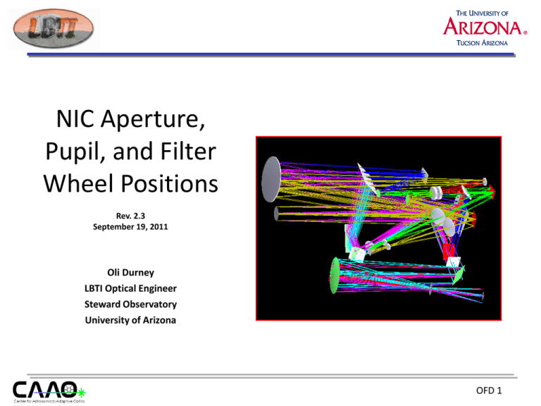
NIC Aperture, Pupil, and Filter Wheel Positions Rev. 2.3 September 19, 2011 Oli Durney LBTI Optical Engineer Steward Observatory University of Arizona OFD 1 Revision History PowerPoint File Name NIC Mechanisms Version Date Modified Changes from Previous Version NIC Wheel Positions v1.0.ppt 1.0 01-26-11 Original version, PhaseCam wheels (Pupil, FW1, FW2, ND) NIC Wheel Positions v1.1.ppt 1.1 01-27-11 Include CAD drawing of ND wheel, added Prism & Optics wheels NIC Wheel Positions v1.2.ppt 1.2 02-01-11 Flip Prism and Optics CAD orientations, colorize filters, change titles NIC Wheel Positions v1.3.ppt 1.3 02-03-11 Update Notes, add Optics & Prism cell exploded views, add NAC wheel, re-order slides NIC Wheel Positions v1.4.ppt 1.4 02-15-11 Add LMIRCam Filter wheels #1-4, add LMIRCam Aperture wheel NIC Wheel Positions v1.5.ppt 1.5 02-21-11 Revise ‘drawn as’ comment, add red circle for optical axis and Note NIC Wheel Positions v1.6.ppt 1.6 03-08-11 Change filters in LMIRCam FW#2 NIC Wheel Positions v1.7.ppt 1.7 04-20-11 Add Large & Small Beam Diverter, Image Dichroic, ID 3D view, Left & Right Shutter NIC Wheel Positions v1.8.ppt 1.8 04-20-11 Add ‘controlled by’ comment, add NAC Source NIC Wheel Positions v1.9.ppt 1.9 04-22-11 Add Shutter 3D views NIC Wheel Positions v2.0.ppt 2.0 04-28-11 Reverse rotation direction and order of NAC wheel, add pinholes in Pos 3 & 6 NIC Wheel Positions v2.1.ppt 2.1 04-29-11 Reverse rotation direction and order of LMIRCam FW#2, Add Revision History NIC Wheel Positions v2.2.ppt 2.2 05-03-11 Add ‘Steps’ column to all slides, situate ‘Home’ in between Pos 5&6 on NAC slide, revise text on Image Dichroic slide, add red optical axis to all other slides, revise ‘Note’ accordingly NIC Wheel Positions v2.3.ppt 2.3 09-19-11 Add 12-hole and 24-hole aperture masks in Pos 6&7 of LMIRCam FW#1, illustration shows installed orientation of hole patterns OFD 2 ND Wheel - Assembly • Neutral Density filter set: P/N FX90-0100 from Janos Technology • Drawn as viewed with cover plate removed from Access Port side (side facing PICNIC Detector) • CW rotation of motor = CW rotation of wheel Position Steps Description Dimensions 1 (Home) Open f=25.4mm 2 OD=0.50, T=31.62% f=25.4mm, t=1mm 3 OD=1.00, T=10.00% f=25.4mm, t=1mm 4 OD=2.00, T=1.00% f=25.4mm, t=1mm 5 OD=3.00, T=0.10% f=25.4mm, t=1mm CW 1 • Controlled by Motor Box #2, Drive #1 NOTE: Optical Axis (Exit Port) is shown in red and is located at Position 1 when Wheel is in the Home position, Pos 1 will be replaced with an A/R coated ZnSe window OFD 3 Optics Wheel – Assembly • CaF2 re-imaging lenses from ISP Optics • Drawn as viewed with cover plate removed from flat side (side facing PICNIC Detector) • CW rotation of motor = CW rotation of wheel Position Steps Dimensions 1 (Home) Open Open 2 Dual Large Lenses f=9.5mm, t=2.8mm 3 Open Open 4 Mixed Large/Small f=9.5mm, t=2.8mm Lenses f=8.5mm, t=2.8mm 5 Open Open 6 Dual Small Lenses f=8.5mm, t=2.8mm 4 Description CW 1 • Controlled by Motor Box #2, Drive #2 NOTE: Optical Axis (Exit Port) is shown in red and is located at Position 1 when Wheel is in the Home position OFD 4 Optics Wheel – Cells Dual Large Lenses Mixed Large/Small Lenses Dual Small Lenses OFD 5 Prism Wheel - Assembly • Neutral Density filter set: P/N FX90-0100 from Janos Technology • Drawn as viewed with cover plate removed from Baffle Tube side (side facing Field Lenses) • CW rotation of motor = CW rotation of wheel Position Steps Dimensions 1 (Home) Open Open 2 Dual Triplet Prisms 12x12mm 3 H Filter f=25.4mm 4 Single Triplet Prism 12x12mm 1 Description CW 4 • Controlled by motor Box #2, Drive #3 with H Filter 5 K Filter f=25.4mm 6 Single Triplet Prism 12x12mm with K Filter NOTE: Optical Axis (Entrance Port) is shown in red and is located at Position 1 when Wheel is in the Home position OFD 6 Prism Wheel – Cells Dual Triplet Prisms Single Triplet Prism with Filter OFD 7 NAC Aperture Wheel • ZnSe lenses and mirror from Edmund Optics • Drawn as viewed from cryostat Window side • CWW rotation of motor = CWW rotation of wheel • Controlled by Motor Box #2, Drive #4 4 Position Steps Name Size 1 (Home) 0 Open 42.86 x 42.86mm 2 100000 ZnSe Lens and 45° f=25.4mm Fold Mirror 3 200000 5 mm Aperture f=25.4mm 4 300000 Znse Lens f=25.4mm 5 400000 3x3 Grid of Pinholes 36.46 x 36.46mm CCW f=1mm, d=8.94mm 6 500000 50 mm Pinhole f=25.4mm 1 NOTE: Optical Axis (Entrance Port) is shown in red and is located at Position 1 when Wheel is in the Home position OFD 8 NAC Source Slide • Wires installed on 03-07-11 • Drawn as viewed from cryostat Window side • CW rotation of motor = vertical translation of the slide ?? • Controlled by Motor Box #1, Drive #7 AWG Size 1 30 0.0100” 2 40 0.0310” 3 40 0.0310” 4 48 0.0012” 5 48 0.0012” 30 0.0100” 40 0.0310” 8 40 0.0310” 9 48 0.0012” 10 48 0.0012” 6 7 (Home) Steps 1 2 3 4 5 6 7 8 9 10 Move Position 1 2 3 4 5 6 7 8 9 10 Back View NOTE: Pos 6-10 are not currently working (05-03-11). However, the wires are installed. OFD 9 LMIRCam Filter Wheel #1 • Single Apertures installed on 01-21-11, Hole patterns installed on 09-16-11 • Drawn as viewed with cover plate removed from Baffle Tube side (side facing LMIRCam Dichroic) • CW rotation of motor = CCW rotation of wheel • Controlled by LMIRCam Motor Box, Drive #1 Size 1 (Home) Open 25.4mm 2 Small Dual Aperture f~7.19mm 3 Large Dual Aperture f~7.49mm 4 Left Aperture f~8.16mm 5 Right Aperture f~8.21mm 6 24-hole Pattern 25.4mm 7 12-hole Pattern 25.4mm 8 Open 25.4mm 9 Open 25.4mm 10 Open 25.4mm 11 Pinhole ~0.33mm 12 Blank 25.4mm 4 Name 10 Steps 7 Position NOTE: Optical Axis (Entrance Port) is shown in red and is located at Position 1 when Wheel is in the Home position CCW 1 OFD 10 LMIRCam Filter Wheel #2 • All filter retainer rings adjusted on 01-19-11, H & J filters installed on 03-08-11 • Drawn as viewed with cover plate removed from flat side (side facing LMIRCam Baseplate) • CCW rotation of motor = CCW rotation of wheel • Controlled by LMIRCam Motor Box, Drive #2 Size 1 (Home) Open 25.4mm 2 Ks (2.00-2.32 mm) 25.4mm 3 H (1.50-1.81 mm) 25.4mm 4 J (1.18-1.36 mm ) 25.4mm 5 L-spec (2.81-4.00 mm) 25.4mm 6 M-long (4.60-5.86 mm) 25.4mm 7 Std ‘M’ (4.60-4.97 mm) 25.4mm 8 L-long 2 (3.81-4.05 mm) 25.4mm 9 L-long 1 (3.51-4.06 mm) 25.4mm 10 Std ‘L’ (3.41-3.99 mm) 25.4mm 11 L-short (3.10-3.51 mm) 25.4mm 12 Blank 25.4mm 10 Name NOTE: Optical Axis (Exit Port) is shown in red and is located at Position 1 when Wheel is in the Home position 4 Steps 1 Position CCW 7 OFD 11 LMIRCam Filter Wheel #3 • New filter (Pos 10) installed on May 11, 2010 • Drawn as viewed with cover plate removed from Baffle Tube side (side facing Biconic #2) • CW rotation of motor = CCW rotation of wheel • Controlled by LMIRCam Motor Box, Drive #3 Size 1 (Home) Open 25.4mm 2 H2O Ice 1 (2.96-3.12 mm) 25.4mm 3 H2O Ice 2 (3.01-3.15 mm) 25.4mm 4 PAH 1 (3.26-3.31 mm) 25.4mm 5 PAH 2 (3.38-3.43 mm) 25.4mm 6 Br-a (4.02-4.09 mm) 25.4mm 7 Br-a off (3.97-4.04 mm) 25.4mm 8 L-cont 1 (3.13-3.20 mm) 25.4mm 9 L-cont 2 (3.39-3.54 mm) 25.4mm 10 L-cont 3 (3.55-3.64 mm) 25.4mm 11 L-cont 4 (3.68-3.88 mm) 25.4mm 12 Blank 1 Name 7 Steps 4 Position CCW 10 25.4mm NOTE: Optical Axis (Entrance Port) is shown in red and is located at Position 1 when Wheel is in the Home position OFD 12 LMIRCam Filter Wheel #4 • PK-50 Blocker not installed because of OD clearance concern (substrate delivered with 2 chips) • Drawn as viewed with cover plate removed from Baffle Tube side (side facing detector) • CW rotation of motor = CW rotation of wheel • Controlled by LMIRCam Motor Box, Drive #4 Size 1 (Home) Open 25.4mm 2 Blank 25.4mm 3 PK-50 Blocker 25.4mm 4 Pupil Imaging Lens (ZnSe)12.7mm 5 Open 25.4mm 6 Open 25.4mm 7 Open 25.4mm 8 Open 25.4mm 9 Open 25.4mm 10 Open 25.4mm 11 Open 25.4mm 12 Open 25.4mm 7 Name NOTE: Optical Axis (Exit Port) is shown in red and is located at Position 1 when Wheel is in the Home position 1 Steps 4 Position CW 10 OFD 13 LMIRCam Aperture Wheel • New filter (Pos 10) installed on May 11, 2010 • Drawn as viewed with cover plate removed from side opposite cryo-motor (side facing Biconic #2) • CW rotation of motor = CW rotation of wheel Position Steps Size 1 (Home) Open 50.8x50.8mm 2 Open 50.8x50.8mm 3 Pinhole 1mm? 4 Blank 50.8x50.8mm 3 Name 1 2 • Controlled by LMIRCam Motor Box, Drive #5 CW 4 NOTE: Optical Axis (Exit Port) is shown in red and is located at Position 1 when Wheel is in the Home position OFD 14 Large Beam Diverter Slide • Two (2) possible configurations for the Beam Diverter – Large (2-position) and Small (3-position) Move • Drawn as viewed from entrance Window • CW rotation of motor = right translation of the slide ?? • Controlled by Motor Box #1, Drive #6 Position Steps Name Size 1 (Home) Open 72x57mm 2 Large Dichroic 74x58x7mm Position of 1 when 2 is centered along the optical axis 1 2 NOTE: Position 1 nominally houses the Large Mirror. It is currently removed to allow an open path to LMIRCam Optical Axis is shown in red and is located at Position 1 when Slide is in the Home position OFD 15 Image Dichroic Slide • Drawn as viewed from entrance Window • CW rotation of motor = right translation of the slide ?? • Controlled by Motor Box #1, Drive #1 Move Position Steps Name Size 1 (Home) Open 72x57mm 2 Large Dichroic 74x58x7mm 1 2 NOTE: Optical Axis is shown in red and is located at Position 1 when Slide is in the Home position OFD 16 Image Dichroic Assembly Front View ISO View Side View OFD 17 Right Shutter • Shutter located in front of Fixed Nulling Mirror • Drawn as viewed from entrance Window • Controlled by Motor Box #1, Drive #2 Position Steps Name Size 1 (Home) Vertical – half open 20mm 2 Closed 20mm 3 Horizontal – half open 20mm 4 Open 20mm 1 2 3 4 NOTE: Optical Axis is shown in red OFD 18 Left Shutter • Shutter located in front of Field Steering Mirror • Drawn as viewed from entrance Window • Controlled by Motor Box #1, Drive #3 Position Steps Name Size 1 (Home) Vertical – half open 20mm 2 Closed 20mm 3 Horizontal – half open 20mm 4 Open 20mm 1 2 3 4 NOTE: Optical Axis is shown in red OFD 19 Shutter Assemblies Left Shutter Right Shutter OFD 20 Additional Slides OFD 21 Small Beam Diverter Slide • Two (2) possible configurations for the Beam Diverter – Large (2-position) and Small (3-position) • Drawn as viewed from entrance Window Move Move • Controlled by Motor Box #1, Drive #6 Position Steps Name Size 1 Open 42x30mm 2 (Home) Small Mirror 52x32x9.53mm 3 Small Dichroic 54x38x7mm 1 2 3 NOTE: Position 1 is Open when slide is moved to Position 2. It is Small Mirror when slide is moved to Position 3 Optical Axis is shown in red and is located at Position 2 when Slide is in the Home position OFD 22


