Inter Regional Processor
advertisement
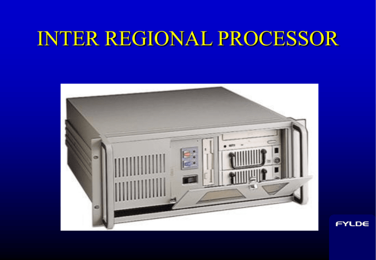
INTER REGIONAL PROCESSOR DESIGN PHILOSOPHY Based on industry standard pc hardware. Industrial specification IBM compatible computer running Fylde IRP software. Equipped with a multi port communications controller. Built in Hardware Watchdog. WHAT IS IT? Allows inter regional expansion for Fylde trunking systems. Connects up to 16 regions (RCPs) to form a wide area trunking network. Routes audio/data between inter regional radio sites. IMPLEMENTATION Connected to the RCPs by standard RS232 communication links. Audio can be routed via: –direct connection of audio circuits between RCPs –Fylde PCM Switch at the IRP –both of above FACILITIES 1 Status Display showing: –RS232 link status to RCPs –IRP integrated PCM Switch (if connected) –Processor Loading –Calls in progress –Printer status FACILITIES 2 Logging Facilities: –Call Log –Registration log Incorporated Registration Database allows: –reduced system load –speed up call processing –De-registration of RU’s FACILITIES 3 Diagnostic Facilities: –Node Communications - monitoring of data messages between IRP and RCP –PCM Switch Communications - similar to Node Communications –Silicon Disk Memory Test - allows testing of the disk used to store the Registration Database INITIAL CONFIGURATION General Program Parameters –Registration Validity Period –Maximum Allowable Prefix –Call Logging Facilities –Disk Drive for Registration Database –Disk Drive for logging files –Call Log page length –Log Registration Records to disk –Change Main Password INITIAL CONFIGURATION Configure the RS232 links from each region –baud rate –No parity / 8 data bits / 1 stop bit Configure the PCM Switch *EVEN IF NO PCM SWITCH IS PRESENT* –communications port on the IRP pc –link baud rate (usually 9600) –PCM Switch Patch Map IRP PATCH MAP 1 Determines the audio inter connect between sites and regions, by either: –routing audio circuits through a PCM Switch – direct connection which does not require a PCM switch. Used for low capacity networks –both above options –Can only use direct connection with Inter-Regional group calls on 2 region systems. IRP PATCH MAP 2 Maximum of 24 (0-23) lines available Each region has 24 lines available but not the facility to use them all, at each region Each region must be configured separately. IRP PATCH MAP 3 Configuration –Two parameters for each audio line FITTED and PCM SWITCH PORT –FITTED is set YES or NO, indicating whether that line is fitted to that region –PCM SWITCH PORT determines the port used between 1 and 128. If set to 0 (zero) then this indicates that that line is a direct connection between RCPs. Blank indicates not fitted. IRP PATCH MAP 4 IRP RCP REGION 1 LINE 0 LINE 1 LINE 2 LINE 3 1 2 3 4 7 8 PCM 9 5 6 10 LINE 0 LINE 1 LINE 2 LINE 3 RCP REGION 3 LINE 4 - 7 RCP REGION 2 LINE 0 LINE 1 3 REGION EXAMPLE IRP PATCH MAP 5 LINE FITTED PORT LINE FITTED PORT LINE FITTED PORT 0 1 2 3 4 5 6 7 YES YES YES YES YES YES YES YES 1 2 3 4 0 0 0 0 0 1 2 3 4 5 6 7 YES YES NO NO YES YES YES YES 5 6 0 1 2 3 4 5 6 7 YES YES YES YES NO NO NO NO 7 8 9 10 0 0 0 0 BOOT OPERATION Should be run from Floppy Disk. Use Hard Disk Boot as back up only. Ensure configuration is the same on both floppy and hard disk.

