Pelton wheel - Repositories
advertisement
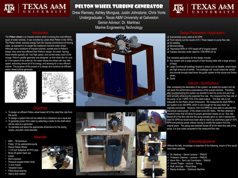
Pelton Wheel Turbine Generator Drew Ramsey, Ashley Munguia, Justin Johnstone, Chris Yonts Undergraduate – Texas A&M University at Galveston Senior Advisor: Dr. Martinez Marine Engineering Technology Introduction The Pelton wheel is an impulse turbine which is among the most efficient types of water turbines. It was invented by Lester Allan Pelton in the 1870s. The Pelton wheel extracts energy from the impulse (momentum) of moving water, as opposed to its weight like traditional overshot water wheel. Although many variations of impulse turbines existed prior to Pelton's design, they were less efficient than Pelton's design; the water leaving these wheels typically still had high speed, and carried away much of the energy. Pelton's paddle geometry was designed so that when the rim runs at ½ the speed of the water jet, the water leaves the wheel with very little speed, extracting almost all of its energy, and allowing for a very efficient turbine. The purpose of this project is to design and construct an efficient pelton wheel turbine generator. Design Parameters / Applications Submersible pump rated at 52 GPM Fluid velocity out the nozzle of 81.7 ft/sec based on pump flow rate No welding Minimal bolting Theoretical RPM of 1575 based off of angular speed 3 phase induction motor rated for 1750 RPM 3/4 hp The industrial applications for this design include: Any system with a large amount of free flowing water with a large amount of head. Large Commercial buildings located in areas such as Seattle, where there are high amounts of rainfall. The buildings roof would collect the rainfall and provide enough head down the gutter system to the nozzle and Pelton wheel. Dams Results / Modifications Objectives To design an efficient Pelton wheel based off of the rated flow rate from the pump. To design a system that can be rolled into a classroom as a visual aid. To generate power from water by attaching a motor to the shaft which will be used as a generator. To calculate and select the appropriate dimensions for the piping, nozzle, and pitch circle diameter. After completing the fabrication of the system, we tested the system and did not reach the performance expectations of the overall machine. Therefore, after troubleshooting the system we decided to test the pump and see if we were actually achieving the expected flow rate. We measured the flow rate of the pump to be 7 GPM (13% of its rated output). This flow rate is not adequate for the Pelton wheel dimensions. We measured the shaft RPM of our system to be 350 RPM, which is not enough for the size motor we originally purchased. However, from this RPM we were able to calculate the theoretical output power of the wheel to be 220 Watts. We then obtained a treadmill motor that will allow for power generation based on our flow rate. Based off of the flow rate that the pump actually gave us, had it reached the rated 52 GPM we would have been able to reach our preliminary goal of 1575 RPM and produce power without having to modify the system from the original plans. The piping was selected based off of the rated flow rate of the pump, it is over sized compared to the measured flow rate. Materials • • • • • • • • • • • • 6061 – T6 Aluminum Flotec 1/3 hp submersible pump Pamor Pelton Wheel 1-1/2 inch Schedule 40 PVC pipe Brute 20 gallon trash can Lexan Birch plywood Pressure treated timber (4x4) ½ inch nozzle Treadmill motor Pillow block bearing Heavy duty casters Acknowledgements Without the help, knowledge or expertise of the following, known of this would have been possible: Dr. Martinez – Senior Lecturer – TAMUG Professor Coleman – Lecturer – TAMUG Kevin Win – Tech Lab Coordinator – TAMUG Vincent Treglia – Lecturer – Tamug Ruth Jennings – Wood Shop Randy Andersen – Dickinson Machine
