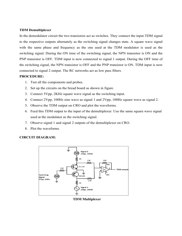
TDM Demultiplexer In the demodulator circuit the two transistors act as switches. They connect the input TDM signal to the respective outputs alternately as the switching signal changes state. A square wave signal with the same phase and frequency as the one used at the TDM modulator is used as the switching signal. During the ON time of the switching signal, the NPN transistor is ON and the PNP transistor is OFF. TDM input is now connected to signal 1 output. During the OFF time of the switching signal, the NPN transistor is OFF and the PNP transistor is ON. TDM input is now connected to signal 2 output. The RC networks act as low pass filters. PROCEDURE: 1. Test all the components and probes. 2. Set up the circuits on the bread board as shown in figure. 3. Connect 5Vpp, 2KHz square wave signal as the switching input. 4. Connect 2Vpp, 100Hz sine wave as signal 1 and 2Vpp, 100Hz square wave as signal 2. 5. Observe the TDM output on CRO and plot the waveforms. 6. Feed this TDM output to the input of the demultiplexer. Use the same square wave signal used at the modulator as the switching signal. 7. Observe signal 1 and signal 2 outputs of the demultiplexer on CRO. 8. Plot the waveforms. CIRCUIT DIAGRAM: TDM Multiplexer TDM Demultiplexer WAVEFORM: RESULT: TDM Multiplexer and demultiplexer circuits were set up and the waveforms were plotted. INFERENCE: Learned the basic idea of TDM multiplexing and demultiplexing. Note: The demultiplexed outputs should be perfect sine and square waves. But with the given demultiplexer, the signal 2 output w be employed to make the output a perfect square wave.
