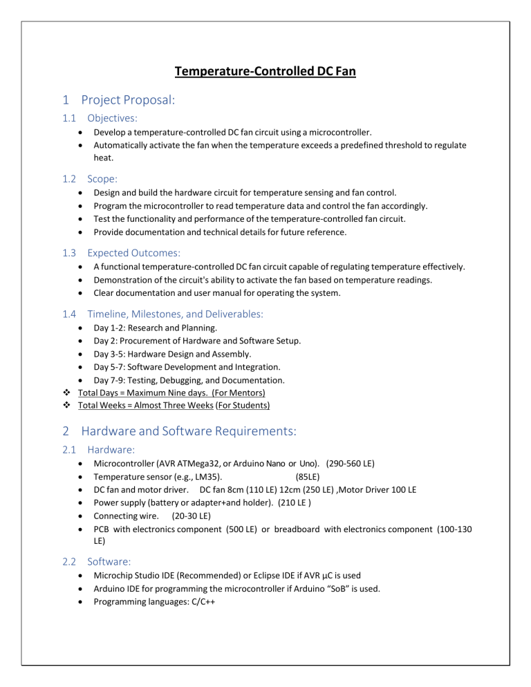
Temperature-Controlled DC Fan 1 Project Proposal: 1.1 Objectives: Develop a temperature-controlled DC fan circuit using a microcontroller. Automatically activate the fan when the temperature exceeds a predefined threshold to regulate heat. 1.2 Scope: Design and build the hardware circuit for temperature sensing and fan control. Program the microcontroller to read temperature data and control the fan accordingly. Test the functionality and performance of the temperature-controlled fan circuit. Provide documentation and technical details for future reference. 1.3 Expected Outcomes: A functional temperature-controlled DC fan circuit capable of regulating temperature effectively. Demonstration of the circuit's ability to activate the fan based on temperature readings. Clear documentation and user manual for operating the system. 1.4 Timeline, Milestones, and Deliverables: Day 1-2: Research and Planning. Day 2: Procurement of Hardware and Software Setup. Day 3-5: Hardware Design and Assembly. Day 5-7: Software Development and Integration. Day 7-9: Testing, Debugging, and Documentation. Total Days = Maximum Nine days. (For Mentors) Total Weeks = Almost Three Weeks (For Students) 2 Hardware and Software Requirements: 2.1 Hardware: Microcontroller (AVR ATMega32, or Arduino Nano or Uno). (290-560 LE) Temperature sensor (e.g., LM35). (85LE) DC fan and motor driver. DC fan 8cm (110 LE) 12cm (250 LE) ,Motor Driver 100 LE Power supply (battery or adapter+and holder). (210 LE ) Connecting wire. (20-30 LE) PCB with electronics component (500 LE) or breadboard with electronics component (100-130 LE) 2.2 Software: Microchip Studio IDE (Recommended) or Eclipse IDE if AVR µC is used Arduino IDE for programming the microcontroller if Arduino “SoB” is used. Programming languages: C/C++ 3 Design and Implementation: 3.1 Hardware Design: Design the circuit layout for connecting the microcontroller, temperature sensor, and fan. Connect the temperature sensor to the microcontroller to read temperature data. Connect the fan and motor driver to the microcontroller for fan control. Ensure proper power supply and grounding for reliable operation. 3.2 Software Implementation: Program the microcontroller to read temperature data from the sensor. Implement logic to activate the fan when the temperature exceeds the threshold. Test the software code for accurate temperature readings and fan control. 4 Testing and Debugging: Conduct tests to verify the functionality of the temperature-controlled fan circuit. Test the responsiveness of the fan control system to changes in temperature. Debug any issues encountered during testing and refine the code for optimal performance. 5 Documentation: 5.1 Design Documentation: Schematics and diagrams illustrating the hardware connections and circuit layout. Explanation of the software architecture and control algorithms used. 5.2 Implementation Documentation: Code documentation with detailed comments and explanations. Description of hardware assembly and software development processes. 5.3 Testing Documentation: Test plans outlining test cases and expected outcomes. Test results and analysis highlighting strengths and areas for improvement. 5.4 User Manual: Instructions for setting up the temperature-controlled DC fan circuit. Guidelines for configuring the temperature threshold and fan activation settings. Troubleshooting guide for common issues encountered during operation. 6 Presentation: Overview of the project's objectives, design, implementation, testing, and debugging processes. Demonstration of the temperature-controlled DC fan circuit's functionality. Discussion of future enhancements and potential applications of the system. By following this structure, the report will provide a comprehensive overview of the Temperature Controlled DC Fan project, ensuring clarity and usability for readers and stakeholders.


