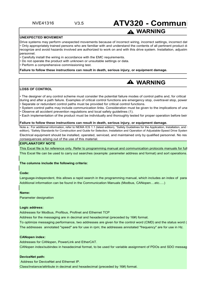
NVE41316 V3.5 ATV320 - Communication Pa WARNING UNEXPECTED MOVEMENT Drive systems may perform unexpected movements because of incorrect wiring, incorrect settings, incorrect data or other errors. • Only appropriately trained persons who are familiar with and understand the contents of all pertinent product documentation and who h recognize and avoid hazards involved are authorized to work on and with this drive system. Installation, adjustment, repair and maintena personnel. • Carefully install the wiring in accordance with the EMC requirements. • Do not operate the product with unknown or unsuitable settings or data. • Perform a comprehensive commissioning test. Failure to follow these instructions can result in death, serious injury, or equipment damage. WARNING LOSS OF CONTROL • The designer of any control scheme must consider the potential failure modes of control paths and, for critical control functions, provid during and after a path failure. Examples of critical control functions are emergency stop, overtravel stop, power outage and restart. • Separate or redundant control paths must be provided for critical control functions. • System control paths may include communication links. Consideration must be given to the implications of unanticipated transmission • Observe all accident prevention regulations and local safety guidelines (1). • Each implementation of the product must be individually and thoroughly tested for proper operation before being placed into service. Failure to follow these instructions can result in death, serious injury, or equipment damage. Note a.: For additional information, refer to NEMA ICS 1.1 (latest edition), “Safety Guidelines for the Application, Installation, and Maintenance of Solid State C edition), “Safety Standards for Construction and Guide for Selection, Installation and Operation of Adjustable-Speed Drive Systems.” Electrical equipment should be installed, operated, serviced, and maintained only by qualified personnel. No responsibility is assumed by consequences arising out of the use of this material. EXPLANATORY NOTE This Excel file is for reference only. Refer to programming manual and communication protocols manuals for full information. This Excel file can be used to carry out searches (example: parameter address and format) and sort operations. The columns include the following criteria: Code: Language-independent, this allows a rapid search in the programming manual, which includes an index of parameter codes. Additional information can be found in the Communication Manuals (Modbus, CANopen....etc.....) Name: Parameter designation Logic address: Addresses for Modbus, Profibus, Profinet and Ethernet TCP Address for the messaging are in decimal and hexadecimal (preceded by 16#) format. To optimize messaging performance, two addresses are given for the control word (CMD) and the status word (ETA). The addresses annotated "speed" are for use in rpm; the addresses annotated "frequency" are for use in Hz. CANopen index: Addresses for CANopen, PowerLink and EtherCAT. CANopen index/subindex in hexadecimal format, to be used for variable assignment of PDOs and SDO messaging. DeviceNet path: Address for DeviceNet and Ethernet IP. Class/instance/attribute in decimal and hexadecimal (preceded by 16#) format. When two paths are given, for example: - 16#29/01/0D = 41/1/13 (messaging): ODVA standard path. It can be used for explicit messaging. Do not use it for configuring an assem - 16#8C/01/07 = 140/1/7 (assembly): Altivar-specific path. This is the path that must be used for configuring an assembly. Avoid using it better interchangeability. Link: - For WORD (listing), a dynamic link opens its description. Listings are common to several parameters; only one part is valid for a given manual to determine the valid values. If an invalid value is written to a configuration parameter, the drive will indicate a fault [Invalid conf - For WORD (bit register), in the Type column, a dynamic link opens its description. Category: Defines the role of the parameter, for example: Command parameter, Status parameter, etc. Access: Read and write options: R: Read only R/W: Read and write R/WS: Read and write (write only possible when the drive is not in RUN mode). It is not possible to write these parameters in "5-Operation enabled" or "6-Quick stop active" states. If the parameter is written in the "4-Switched on" state, transition 10 to "2-Switch on disabled" is activated. Type: WORD (bit register): Word where each bit represents a command or a state WORD (listing): Word where each value represents a possible choice for a configuration or state INT: Signed integer UINT: Unsigned integer DINT: Signed double integer UDINT: Unsigned double integer Units: Physical unit and multiplier. Factory setting: Value of the parameter set at the factory. Menu: Indicates the menus or menus where the parameter is located. Menu name displayed on the graphic display terminal, in square brackets 7-segment digits on the integrated display terminal, in round brackets (---). Range: Possible values. Display: Parameter name displayed on the graphic display terminal, in square brackets [---], and parameter code displayed by the 7-segment digi round brackets (---). Menu: Indicates the menus or menus where the parameter is located. Menu name displayed on the graphic display terminal, in square brackets 7-segment digits on the integrated display terminal, in round brackets (---). Order: Gives the initial storage order of the parameter in the file, from 1 to n. This makes it possible, after sorting operations, to put this file bac column in ascending order. mmunication Parameters incorrect data or other errors. ent product documentation and who have received safety training to ation, adjustment, repair and maintenance must be performed by qualified d, for critical control functions, provide a means to achieve a safe state el stop, power outage and restart. cations of unanticipated transmission delays or failures of the link. on before being placed into service. nstallation, and Maintenance of Solid State Control” and to NEMA ICS 7.1 (latest ed Drive Systems.” onnel. No responsibility is assumed by Schneider Electric for any anuals for full information. rt operations. ndex of parameter codes. status word (ETA). use in Hz. SDO messaging. Do not use it for configuring an assembly. nfiguring an assembly. Avoid using it for explicit messaging, to ensure eters; only one part is valid for a given parameter. Refer to programming drive will indicate a fault [Invalid config.] (CFI). d" is activated. ic display terminal, in square brackets [---], and menu code displayed by the code displayed by the 7-segment digits on the integrated display terminal, in ic display terminal, in square brackets [---], and menu code displayed by the sorting operations, to put this file back in its initial order by sorting the


