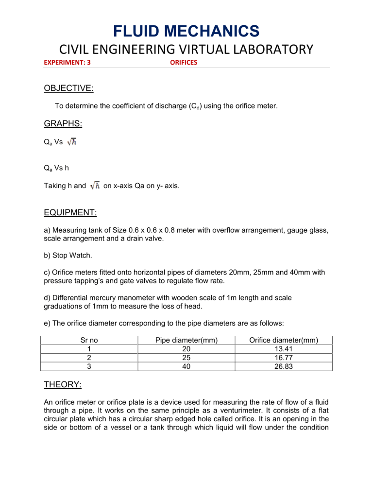
FLUID MECHANICS CIVIL ENGINEERING VIRTUAL LABORATORY EXPERIMENT: 3 ORIFICES OBJECTIVE: To determine the coefficient of discharge (Cd) using the orifice meter. GRAPHS: Qa Vs Qa Vs h Taking h and on x-axis Qa on y- axis. EQUIPMENT: a) Measuring tank of Size 0.6 x 0.6 x 0.8 meter with overflow arrangement, gauge glass, scale arrangement and a drain valve. b) Stop Watch. c) Orifice meters fitted onto horizontal pipes of diameters 20mm, 25mm and 40mm with pressure tapping’s and gate valves to regulate flow rate. d) Differential mercury manometer with wooden scale of 1m length and scale graduations of 1mm to measure the loss of head. e) The orifice diameter corresponding to the pipe diameters are as follows: Sr no 1 2 3 Pipe diameter(mm) 20 25 40 Orifice diameter(mm) 13.41 16.77 26.83 THEORY: An orifice meter or orifice plate is a device used for measuring the rate of flow of a fluid through a pipe. It works on the same principle as a venturimeter. It consists of a flat circular plate which has a circular sharp edged hole called orifice. It is an opening in the side or bottom of a vessel or a tank through which liquid will flow under the condition EXPERIMENT: 3 ORIFICES BSA-CEVL that the liquid surface is always above the top edge of the opening. The orifice diameter is 0.5 times the diameter of the pipe. A differential manometer is connected at section 1 which is at a distance of about 1.5 to 2 times the pipe diameter upstream from the orifice plate, and at section 2, which is at a distance of about half the diameter of the orifice on the downstream side from the orifice plate. The basic principle on which a orifice meter works is that by reducing the cross sectional area of the flow of passage, a pressure difference between the two sections is developed and the measurement of the pressure difference enables the determination of the discharge through pipe. However, an orifice meter is a cheaper arrangement for discharge measurement through pipes and its installation requires a smaller length as compared to venturimeter. 2 EXPERIMENT: 3 ORIFICES BSA-CEVL CO-FFICIENT OF DISCHARGE: The actual discharge, Where a – Area of measuring tank in cm2 h – Height differences in piezometer in cm. t – Time to collect water for a height difference of h cm, measured in seconds. Theoretical discharge By applying the Bernoulli equation to the upstream section and downstream section an expression for the discharge is obtained. Theoretical discharge for venturimeter/orifice meter Qth A1 A2 2 gH w ( A12 A2 2 ) Where 3 EXPERIMENT: 3 ORIFICES BSA-CEVL A1 – The area at inlet side in cm2 A2 – The area at throat in cm2 Hw - Head difference in the manometer, converted to cm of water. g – Acceleration due to gravity (9.81). Coefficient of discharge, OBSERVATIONS: CO-FFICIENT OF DISCHARGE : Sl No Mnometer readings in (cm) HHg H1 Head loss in cm of water h=(H1-H2) Time taken for 10 cm rise of water in sec (t) Actual discharge (Qa) in cm3/sec Theoritical discharge (Qt) in cm3/sec Coefficient of discharge (Cd) H2 1 2 3 4 5 PROCEDURE: (i) Close the valves of inlet pipe, Orifice meter pipe line and manometer. (ii) The gate valve of the pipeline selected for the experimentation is opened. (iii) The needle valves of the corresponding manometer & Orifice meter are opened. (iv) Adjust the control valve kept at the exit side of the Orifice to a desired flow rate and maintain the flow. (v) Note down the readings of manometer & time for 10cm rise in measuring tank. 4 EXPERIMENT: 3 ORIFICES BSA-CEVL (vi) Adjust the gate valve and repeat the experiment. MAINTENANCE: 1. After completing the experiment close the inlet valve and open all the gate valves & needle valves then close them. 2. Drain the water from measuring tank after completing the experiment RESULT: The coefficient of discharge of the Orifice meter Cd = QUIZ: 1) Venacontracta is at a distance of half the diameter of the orifice a) True b) False 2) The orifice diameter is 0.5 times the diameter of the pipe a) True b) False 3) The principle of orifice meter is different from that of the venturimeter a) True b) False REFERENCES: 1) 2) 3) 4) FLUID MECHANICS- RK BANSAL EXPERIMENTS ON FLUID MECHANICS- SARABJIT SINGH WIKIPEDIA The constructor- http://theconstructor.org/ 5 EXPERIMENT: 3 ORIFICES BSA-CEVL PART – 2 ANIMATION STEPS 6 EXPERIMENT: 3 ORIFICES BSA-CEVL PART – 3 VIRTUAL LAB FRAME 7
