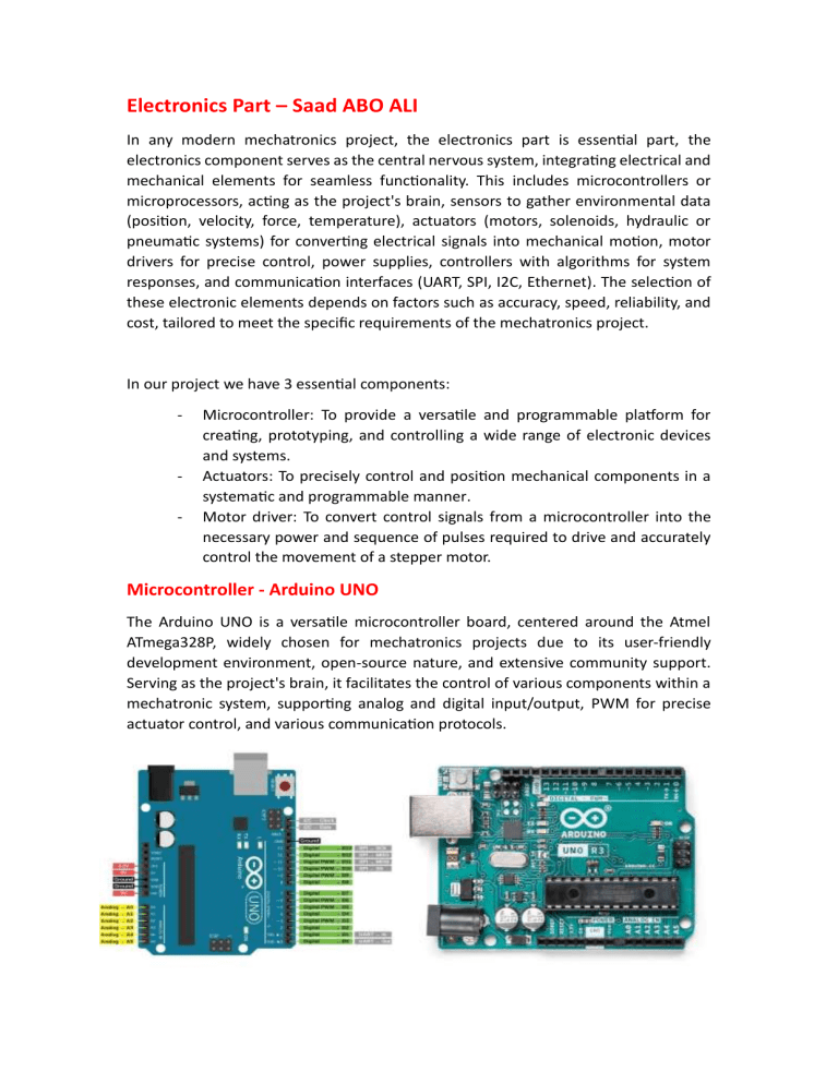
Electronics Part – Saad ABO ALI In any modern mechatronics project, the electronics part is essential part, the electronics component serves as the central nervous system, integrating electrical and mechanical elements for seamless functionality. This includes microcontrollers or microprocessors, acting as the project's brain, sensors to gather environmental data (position, velocity, force, temperature), actuators (motors, solenoids, hydraulic or pneumatic systems) for converting electrical signals into mechanical motion, motor drivers for precise control, power supplies, controllers with algorithms for system responses, and communication interfaces (UART, SPI, I2C, Ethernet). The selection of these electronic elements depends on factors such as accuracy, speed, reliability, and cost, tailored to meet the specific requirements of the mechatronics project. In our project we have 3 essential components: - - Microcontroller: To provide a versatile and programmable platform for creating, prototyping, and controlling a wide range of electronic devices and systems. Actuators: To precisely control and position mechanical components in a systematic and programmable manner. Motor driver: To convert control signals from a microcontroller into the necessary power and sequence of pulses required to drive and accurately control the movement of a stepper motor. Microcontroller - Arduino UNO The Arduino UNO is a versatile microcontroller board, centered around the Atmel ATmega328P, widely chosen for mechatronics projects due to its user-friendly development environment, open-source nature, and extensive community support. Serving as the project's brain, it facilitates the control of various components within a mechatronic system, supporting analog and digital input/output, PWM for precise actuator control, and various communication protocols. STEPPER MOTOR In our project we will use a set of 3 17HS4401 Nema17 and Nema11 Stepper Motors. The NEMA17 stepper motor, belonging to the NEMA standard with a 1.7 x 1.7-inch faceplate, is a popular choice in mechatronics projects due to its precise control over rotational movement. Operating in discrete steps, it offers accuracy and position control, making it ideal for our project since we need a certain level of accuracy because it is a biomedical application on cells. The NEMA17's balance of size, power, and cost contributes to its widespread adoption, with standardized frame sizes ensuring compatibility with various mounting structures. Its ability to hold positions without continuous power and reliability in open-loop control systems makes it valuable for tasks requiring precise motion control in mechatronics projects. STEPPER MOTOR DRIVER Stepper motor driver is an integrated circuit designed to control and regulate the motion of stepper motors by converting digital signals into the appropriate power and sequence of pulses for precise and efficient motor control in various electronic applications. In our project we will use the A4988 stepper motor driver since it has an affordable price and enough functionality for our project. It has also 4 different options of accuracy: 1 step, 1/2 step, 1/4 step and 1/8 step for driving the stepper motor. Electronic Schematic The electronic components of the project will be connected like the below schematic to energize the motors and drivers and drive the motors using the drivers, we will use also a set of 6 limit switches, 2 for both axis to execute the calibration with each start of the system and also to stop the motion of the motors when they arrive to the end of the axis.
